-
MAGNETISM

A piece of matter, which when suspended freely rests itself in a particular direction (north-south) and which possesses a net magnetic moment and which attracts pieces of ferromagnetic materials like Iron, Cobalt, Nickel etc towards it, is called a magnet.

Classically, in general, Magnets are of two types. They are as follows:
(1) Natural magnets:
The magnet which is found in nature is called a natural magnet
e.g. magnetite. \(\left( F{{e}_{3}}{{O}_{3}} \right).\)
Generally they are weak magnets.
(2) Artificial magnets:
The magnets which are artificially prepared are known as artificial magnets. These are generally made of iron, steel and nickel. Waves which are produced due to the periodic vibration of two mutually perpendicular electric and magnetic fields are Electro magnetic waves. It propagates in a direction perpendicular to both electric and magnetic field. e.g. light waves, X-ray, g-ray etc.
- The power of attraction is maximum at the end points of the magnet, these end points are known as poles.
- The north seeking end is called north pole and the south seeking end is called south pole.
- Like poles repel and unlike poles attract.
- The two poles of a magnet can not be isolated.
- The straight line joining the two poles of a bar magnet is called axial line.
- The line passing through the midpoint normal to the axial line is called equatorial line.
- The vertical plane passing through the magnetic axis of a freely suspended bar magnet is called magnetic meridian.
Magnetic poles:
i) If a piece of magnet is dipped in iron filings, they cling to it, especially at certain points. These points are called the poles of the magnet
ii) If a bar-shaped permanent magnet (or) bar magnet is free to rotate, one end points north. This end is called north-seeking end north pole (or) N-pole. The other end is a south pole (or) S-pole.
iii) Unlike poles attract each other and like poles repel each other
iv) The two poles of a magnet can not be isolated.
v) Earth is also a big magnet. Its geographical north pole is close to magnetic south pole. Its geographical south pole is close to its magnetic north pole.
vi) The two poles of the magnet generally are of equal strength and near the ends of the magnet.
vii) The straight line joining the two poles of a bar magnet is called axial line.
viii) The line passing through the midpoint normal to the axial line is called equatorial line.
ix) The vertical plane passing through the magnetic axis of a freely suspended bar magnet is called magnetic meridian.

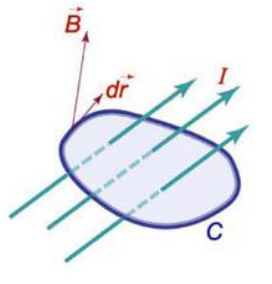
Consider an infinitesimal element of length 'dl' of a wire carrying current I. The magnetic field \(d\vec{B}\) at P because of \(d\vec{l}\) is given by this law
\(d\vec{B}=\frac{{{\mu }_{0}}I(d\vec{\ell }\times \vec{r})}{4\pi \,\,\,\,{{r}^{3}}}\) . . . (i)
Here d\(\vec{\ell }\) is a vector of length dl which is along the direction of current. The product \(Id\vec{\ell }\) is called current element, it is the smallest possible entity causing a magnetic field. A moving charge can also be considered as a current element, we can write
q\(\vec{v}\) = \(d\vec{\ell }\) i then equation (i) can be written asB = \(\frac{{{\mu }_{0}}}{4\pi }\frac{q}{{{r}^{3}}}\left( \vec{v}\times \vec{r} \right)\)

Biot-Savart Law Applications:
Some examples of geometries where the Biot-Savart law can be used to advantage in calculating the magnetic field resulting from an electric current distribution.
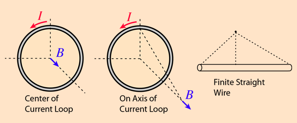
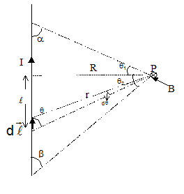
Magnetic Field Due To Current In a Straight Wire :
The magnetic field due to a wire segment carrying current I at P, when the wire segment subtends angles a and b as shown, can be determined as follows:
d\(\vec{B}\) at Pdue to d\(\vec{\ell }\) is : \(dB=\frac{{{\mu }_{o}}}{4\pi }\frac{\,I\,d\vec{\ell }\sin \theta }{{{r}^{2}}}\)
Now, l = R cot q, dl = - R cosec2q.dq, r = R cosec q
\(\begin{align} & \Rightarrow dB=\frac{-{{\mu }_{o}}}{4\pi }\frac{I\,\,(\sin \theta )\,\,(-R\text{cose}{{\text{c}}^{2}}\theta d\theta )}{{{R}^{2}}.\cos e{{c}^{2}}\theta } \\ & B=\frac{-{{\mu }_{o}}I}{4\pi R}\int_{\,\,\beta }^{180-\alpha }{\,\,\,\,\sin \theta d\theta }=\frac{-{{\mu }_{o}}I}{4\pi R}\left[ \cos \alpha +\cos \beta \right] \\ & \text{The magnitude of B = }\frac{{{\mu }_{o}}I}{4\pi R}\,\left[ \cos \alpha +\cos \beta \right] \\ \end{align}\)
= \(\frac{\mu I}{4\pi R}\left[ \sin {{\theta }_{1}}+\sin {{\theta }_{2}} \right]\)
In the vector form
\(\vec{B}=\frac{\mu I}{4\pi R}\left[ \sin {{\theta }_{1}}+\sin {{\theta }_{2}} \right]\) \((-\hat{k})\)

1. Two magnets of magnetic moments of M1, M2 are placed one over the other with like poles touching, the resultant magnetic moment is
Solution :
M1 + M2
2. A magnetised wire of magnetic length ‘2 l’, pole strength ‘m’ and magnetic moment ‘M’ is bent at angle is radian at the centre of the circle, then
Solution :
- Its pole strength remains same
- Its length decreases and becomes \(\left[ \frac{4l\sin \left( \frac{\theta }{2} \right)}{\theta } \right]\)
- Its new magnetic moment becomes \(\left[ \frac{2M\sin \left( \frac{\theta }{2} \right)}{\theta } \right]\)

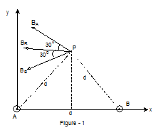
1. Two straight infinitely long and thin parallel wires are spaced 0.1 m apart and carry a current of 10 ampere each. Find the magnetic field at a point distance 0.1 m from both wires in the two cases when the currents are in the (a) same and
Solution :
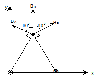
The point P is situated equidistant from the wires A and B. Hence for the given case the magnitude of the magnetic field at P due to both the wires will be same.
BA = BB = B = \(\,\,\frac{{{\mu }_{0}}\,\,\,I}{2\pi \,\,d}\,\,\,=\,\,2\,x{{10}^{-7}}\,\,x\,\,\frac{10}{0.1}\,=\,\,2\,x\,{{10}^{-5}}\,T\)
(a) If the wire carries current in the same direction BA and BB will have the directions as shown in the figure.
The net magnetic field
\({{\overrightarrow{B}}_{R}}\,\,=\,\,2\,B\,\cos \,{{30}^{0}}\,\left( -\hat{i} \right)\)= \(2\sqrt{3}\,\,x\,\,{{10}^{-5}}\,T\,\) along negative x-axis
2. Two straight infinitely long and thin parallel wires are spaced 0.1 m apart and carry a current of 10 ampere each. Find the magnetic field at a point distance 0.1 m from both wires in the two cases when the currents are in the (b) Opposite directions
Solution :
(b) If the wires carry current in opposite directions. The magnetic field at P due to wires A and B will be as shown in figure
The net magnetic field
\({{\overrightarrow{B}}_{R}}\,\,=\,\,2\,B\,\,\cos {{60}^{0}}\,(+\hat{j})\)

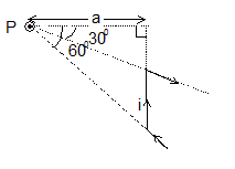
1. Find the magnitude and direction of magnetic field at point P due to the current carrying wire as shown.
Solution :
\(\vec{B}=\frac{\mu i}{4\pi R}\left[ \sin {{\theta }_{1}}+\sin {{\theta }_{2}} \right]\) \((\hat{k})\)
Here q1 = - 300, q2 = 600, putting these values We get,
\(\vec{B}\) = \(\frac{{{\mu }_{0}}i}{4\pi a}\left[ -1/2+\sqrt{3}/2 \right](\hat{k})\)
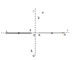
2. A pair of stationary and infinitely long bent wires is placed in the x –y plane as shown in figure. Each wire carries current of 10 amp. The segments L and M are along the x-axis. The segments P and Q are parallel to the y-axis such that OS =
OR = 0.02m. Find the magnitude and direction of the magnetic induction at the origin O
Solution :
As point O is along the length of segments L and M so the field at O due to segments will be zero. Also point O is near one end of a long wire.
The resultant field at O, \({{\overrightarrow{B}}_{R}}\,\,=\,\,{{\overrightarrow{B}}_{P}}\,\,+\,\,{{\overrightarrow{B}}_{Q}}\)
\({{\overrightarrow{B}}_{R}}\,\,=\,\,\frac{{{\mu }_{0}}\,\,\,I}{4\pi \,\,RO}\,\left( {\hat{k}} \right)+\,\frac{{{\mu }_{0}}\,\,\,I}{4\pi \,\,SO}\,\left( {\hat{k}} \right)\)
But RO = SO = 0.02 m
Hence \({{\overrightarrow{B}}_{R}}\,\,=\,\,2\,\,x\,\,\frac{{{\mu }_{0}}}{4\pi }\,\,x\,\,\frac{10}{0.02}\,\left( {\hat{k}} \right)\,\,=\,\,2\,\,x\,{{10}^{-7}}\,\frac{10}{0.02}\,\left( {\hat{k}} \right)\,\,=\,\,{{10}^{-4}}\left( \frac{Wb}{{{m}^{2}}} \right)\,\left( {\hat{k}} \right)\)

1. Current I flows through the wire as shown in the figure. The semi-circular part of the wire is perpendicular to the x-y plane. Find the magnetic field at the centre C of the semi-circle.
Solution:
First we determine the direction of the magnetic field due to the straight parts of the wire. Magnetic field due to the two straight parts is directed into the page i.e. along negative z-axis. Magnetic field due to the semi-circular part is directed along CO.
Now magnitude of the magnetic field due to any one of the straight parts is
\({{B}_{1}}\ =\ \frac{{{\mu }_{0}}\ I}{4\pi \ a}\ \left[ \operatorname{Sin}\ {{90}^{o}}-\operatorname{Sin}\ {{45}^{o}} \right]\,\,\,\)
= \(\frac{{{\mu }_{0}}\ I}{4\pi \ a}\ \left( 1-1/\sqrt{2} \right)\) (along z-direction)
Magnetic field due to the semi-circular part BZ = \(\frac{{{\mu }_{0}}\ I}{2\ \sqrt{2}\ a}\) (Radius of the semi circle is \(\sqrt{2}\ a\))
Now unit vector along CO = ‑ \(\frac{1}{\sqrt{2}}\ (\hat{i}+\hat{j})\)
\ The resultant magnetic field at C.
\(\vec{B}\ =\ 2\frac{{{\mu }_{0}}\ I}{4\pi \ a}\left( \frac{1}{\sqrt{2}}-1 \right)\ \hat{k}-\frac{{{\mu }_{0}}\ I}{4\ a}(\hat{i}+\hat{j})\)
= - \(\frac{{{\mu }_{0}}\ I}{4\ a}\left[ \hat{i}+\hat{j}+\frac{(2-\sqrt{2})}{\pi }\hat{k} \right]\)
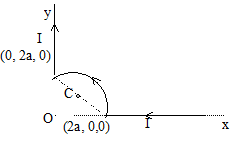
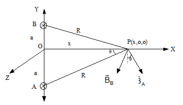
2. A straight segment OC (of length L meter) of a circuit carrying a current Iamp is placed along the x - axis. Two infinitely long straight wires A and B, each extending z = -¥ to +¥ are fixed at y = - a metre and y = + a metre respectively, as shown in the
figure. If the wires A and B each carry a current Iamp into the plane of the paper obtain the expression for the force acting on segment OC. What will be the force on OC if the current in the wire B is reversed?
Solution:
Magnetic field BA produced at P(x, 0, 0) due to wire,
BA = moI/2pR, BB = moI/2pR.
Components of BA and BB along x - axis cancel, while those along y - axis add up to give total field.
\(B=2\left( \frac{{{\mu }_{o}}I}{2\pi R} \right)\,\cos \theta =\frac{2{{\mu }_{o}}I}{2\pi R}.\frac{x}{R}=\frac{{{\mu }_{o}}I}{\pi }\frac{x}{({{a}^{2}}+{{x}^{2}})}(along\,\,\,\,-\,y\,direction)\)
The force dF acting on the current element is \(d\bar{F}=I\left( d\bar{l}\times \bar{B} \right)\)
\ dF = \(\frac{{{\mu }_{0}}{{I}^{2}}}{\pi }\frac{xdx}{{{a}^{2}}+{{x}^{2}}}\left[ \because \,\,\,\,\,\sin {{90}^{0}}=1 \right]\)
Þ F = \(\frac{{{\mu }_{0}}{{I}^{2}}}{\pi }\int\limits_{0}^{L}{\frac{xdx}{{{a}^{2}}+{{x}^{2}}}}\) = \(\frac{{{\mu }_{0}}{{I}^{2}}}{2\pi }\ln \frac{{{a}^{2}}+{{L}^{2}}}{{{a}^{2}}}\)
If the current in B is reversed, the magnetic field due to the two wires would be only along x direction and the force on the current along x - direction will be zero.
-
MAGNETISM

Similar to the Gauss’s law of electrostatics, this law provides us short cut methods of finding magnetic field in cases of symmetry. According to this law, the line integral of magnetic field over a closed path (\(\oint{\vec{B}\cdot d\vec{\ell }}\)) is equal to m0 times the net current crossing the area enclosed by that path.
\(\oint{\vec{B}\cdot d\vec{\ell }}\) = m0 inet
Positive direction of current and the direction of the line integral are given by the right hand thumb and curling fingers respectively.
In order to find magnetic field using Ampere’s law the closed path of line integral is generally chosen such the \(\vec{B}\) is either || or ^ to the path line. Also, wherever \(\vec{B}\) is || to the path, its value should be constant.
Or, in a simplified scalar form,
\(\oint{{{B}_{\parallel }}.ds={{\mu }_{0}}I}\)
Thus the line integral (circulation) of the magnetic field around some arbitrary closed curve is proportional to the total current enclosed by that curve
Important Notes:
• In order to apply Ampère’s Law all currents have to be steady (i.e. do not change with time)
• Only currents crossing the area inside the path are taken into account and have some contribution to the magnetic field
• Currents have to be taken with their algebraic signs (those going “out” of the surface are positive, those going “in” are negative)- use right hand’s rule to determine directions and signs
• The total magnetic circulation is zero only in the following cases: -the enclosed net current is zero -the magnetic field is normal to the selected path at any point -the magnetic field is zero
• Ampère’s Law can be useful when calculating magnetic fields of current distributions with a high degree of symmetry (similar to symmetrical charge distributions in the case of Gauss’ Law)

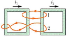
The figure bellow shows two closed paths wrapped around two conducting loops carrying currents \({{i}_{1}}\)and \({{i}_{2}}\). what is the value for integral for (a) path 1 and (b) path 2?
Solution:
To do this you have to use the right hand rule to check whether the currents are positive or negative relative to the part.
(a) On path 1 \({{i}_{1}}\) penetrates in the negative direction while \({{i}_{2}}\) penetrates in the positive direction, so
\(\int{B.ds={{\mu }_{o}}({{i}_{2}}-{{i}_{1}}})\)
(b) On path 2 \({{i}_{1}}\) penetrates twice in the negative direction and \({{i}_{2}}\) once in the negative direction, so
\(\int{B.ds=-{{\mu }_{o}}(2{{i}_{1}}-{{i}_{2}}})\)

1. Suppose that the current density in a wire of radius a varies with r according to J = Kr2, where K is a constant and r is the distance from the axis of the wire. Find the magnetic field at a point distance r from the axis when r < a.
Solution:
Choose a circular path centred on the conductor's axis and apply Ampere's law.
To find the current passing through the area enclosed by the path
IdA = (Kr2) (2prdr) i.e. I = k \(\int\limits_{o}^{r}{\,2\pi {{r}^{3}}dr=\frac{\pi k{{r}^{4}}}{2}}\)
Since \(\int{\vec{B}.d\vec{\ell }}\) = moI Þ B 2pr = mo \(\frac{\pi k{{r}^{4}}}{2}\)
Þ B = \(\frac{{{\mu }_{o}}k{{r}^{3}}}{4}\)
2. Suppose that the current density in a wire of radius a varies with r according to J = Kr2, where K is a constant and r is the distance from the axis of the wire. Find the magnetic field at a point distance r from the axis when r > a.
Solution:
If r > a, then net current through the Amperian loop is
I¢ = \(\int\limits_{0}^{a}{K{{r}^{2}}}\) 2prdr = \(\frac{\pi K{{a}^{4}}}{2}\)
Therefore B = \(\frac{{{\mu }_{o}}K{{a}^{4}}}{4r}\)

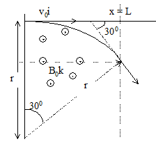
1. The region between x = 0 and x = L is filled with uniform, steady magnetic field B0 k. A particle of mass m, positive charge q and velocity v0
 travels along x-axis and enters the region of magnetic field. Neglect gravity throughout the question. Find the value of L if the particle emerges from the region of magnetic field with its final velocity at an angle 30° to the initial velocity.
Solution:
As the initial velocity of the particle is
perpendicular to the field the particle will move
along the arc of a circle as shown.
If r is the radius of the circle, then
\(\frac{m\ v_{0}^{2}}{r}\ =\ q\ {{v}_{0}}{{B}_{0}}\)
Also from geometry, L = r sin 30°
Þ r = 2L
or L = \(\frac{m\ {{v}_{0}}}{2q\ {{B}_{0}}}\)
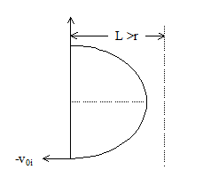
2. The region between x = 0 and x = L is filled with uniform, steady magnetic field B0 k. A particle of mass m, positive charge q and velocity v0
travels along x-axis and enters the region of magnetic field. Neglect gravity throughout the question. Find the final velocity of the particle and the time spent by it in the magnetic field, if the field now extents up to x = 2.1L.Solution:
In this case L = \(\frac{2.1\ m{{v}_{0}}}{2q\ {{B}_{0}}}\ >r\)
Hence the particle will complete semi-circular path and emerge from the field with velocity –v0 \(\hat{i}\)
 as shown.
Time spent by the particle in the magnetic field
\(T=\ \frac{\pi r}{{{v}_{0}}}\) = \(\frac{\pi m}{q\ {{B}_{0}}}\)
The speed of the particle does not change due to magnetic field.

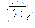
1. A uniform, constant magnetic field \(\vec{B}\) is directed at an angle of 450 to the x-axis in the xy-plane. PQRS is a rigid, square wire frame carrying a steady current I0, with its centre at the origin O. At time t = 0, the frame is at rest in the position shown in the figure, with its sides parallel to the x and y axes. Each side of the frame is of mass M and length L. What is the torque \(\overrightarrow{\tau }\) about O acting on the frame due to the magnetic field?
Solution:
As magnetic field \(\overrightarrow{B}\) is in x-y plane and subtends an angle of 450 with x-axis
Bx = B cos 450 = B/Ö2
And By= = B sin 45 = B/Ö2
So in vector form
\(\overrightarrow{B}\) = \(\hat{i}\,\left( B/\sqrt{2} \right)\,\,+\hat{j}\left( B/\sqrt{2} \right)\)
and \(\overrightarrow{M}\) = \({{I}_{0}}S\hat{k}\,=\,{{I}_{0}}\,{{L}^{2}}\hat{k}\)
so, \(\overrightarrow{\tau }\,\,=\,\,\overrightarrow{M}\,\,x\,\,\overrightarrow{B}\,\,=\,\,{{I}_{0}}\,{{L}^{2}}\,\hat{k}\,\,x\,\,\left( \frac{B}{\sqrt{2}}\hat{i}\,+\,\,\frac{B}{\sqrt{2}}\hat{j} \right)\)
i.e. \(\overrightarrow{\tau }\,\,=\,\,\,\frac{{{I}_{0}}\,{{L}^{2}}\,B}{\sqrt{2}}\,\,x\,(-\hat{i}+\hat{j})\)
i.e., torque has magnitude I0L2 B and is directed along line QS from Q to S.
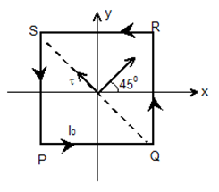
2. A uniform, constant magnetic field \(\vec{B}\) is directed at an angle of 450 to the x-axis in the xy-plane. PQRS is a rigid, square wire frame carrying a steady current I0, with its centre at the origin O. At time t = 0, the frame is at rest in the position shown in the figure, with its sides parallel to the x and y axes. Each side of the frame is of mass M and length L.
Find the angle by which the frame rotates under the action of this torque in a short interval of time Dt, and the axis about which this rotation occurs. (Dt is so short that any variation in the torque during this interval may be neglected). Given moment of inertia of the frame about an axis through its centre perpendicular to its plane is (4/3) ML2.
Solution:
As by theorem of perpendicular axis, moment of inertia of the frame about QS,
IQS = \(\frac{1}{2}\,{{I}_{Z}}\) = \(\frac{1}{2}\,\left( \frac{4}{3}\,M{{L}^{2}} \right)\,\,=\,\,\frac{2}{3}\,\,M{{L}^{2}}\)
And as t = I a,
a = \(\frac{\tau }{I}\,\,=\,\,\frac{{{I}_{0}}\,{{L}^{2}}\,B\,x\,3}{\,2{{L}^{2}}M}\,\,=\,\,\frac{3}{2}\,\,\frac{{{I}_{o}}B}{M}\)
As here a is constant, equations of circular motion are valid and hence from
q = w0t + \(\frac{1}{2}\,\,\alpha \,{{t}^{2}}\) with w0 = 0 we haveq = \(\frac{1}{2}\,\alpha \,{{t}^{2}}\,\,=\,\frac{1}{2}\,\left( \frac{3}{2}\,\frac{{{I}_{0}}B}{M} \right)\,{{\left( \Delta \,t \right)}^{2}}\,\,=\,\,\frac{3}{4}\,\frac{{{I}_{0}}B}{M}\,\,\Delta {{t}^{2}}\)