-
MAGNETISM

When a charged particle having charge 'q' is projected into a magnetic field, it experiences a magnetic force which is given by the expression
\(\vec{F}=q\left( \vec{v}\times \vec{B} \right)\)
Here \(\vec{v}\) = velocity of the particle and
\(\vec{B}\) = magnetic field
Cases of Projection:
Case I : If velocity of charge particle v→ is parallel to B→ then -
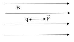
F = q V B Sin 0o ⇒ F = 0
Case II: If a charge enters a magnetic field at right angle to it, it moves in a circular path due to magnetic force which acts as a centripetal force.
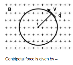
\({{F}_{B}}\to =\frac{m{{V}^{2}}}{r}\)
As we know –
FB = qVB→
Put the value of FB →
\(\therefore \text{ }qVB\text{ }=\frac{m{{V}^{2}}}{r}\)
We can derive multiple relations from the above equation.
Velocity of charge:
\(V=\frac{qBr}{m}\)
Observation: As magnetic field increases the velocity of charge increases.
Radius of circular path:
\(r=\frac{mV}{qB}\)
Observation: To maintain the radius of circular path, as the magnetic field increases the velocity should also increase.
Angular velocity:
\(\begin{align} & V=\frac{qBr}{m}\Rightarrow \text{ }r\omega \text{ }=\frac{qBr}{m} \\ & \therefore \text{ }\omega \text{ }=\frac{qB}{m} \\ \end{align}\)
q/m is known as specific charge.
Observation: Angular velocity depends upon the specific charge and magnetic field.
Time period of rotation:
\(\begin{align} & \omega \text{ }=\frac{2\pi }{T} \\ & \therefore \text{ }T\text{ }=~\frac{2\pi m}{qB} \\ \end{align}\)
Observation: As the magnetic field increases, the angular velocity increases and time period of rotation decreases.
Frequency:
\(\begin{align} & v=\frac{1}{T} \\ & \therefore \text{ }v\text{ }=\frac{qB}{2\pi m} \\ \end{align}\)
Observation: As the time period of rotation increases, the frequency of rotation decreases.
Kinetic energy of the rotating charge:
\(\begin{align} & K.E=\frac{1}{2}m{{v}^{2}} \\ & \therefore \text{ K}\text{.E}=\frac{{{q}^{2}}{{B}^{2}}{{r}^{2}}}{2m} \\ \end{align}\)

1. Moving charge experiences magnetic force because of
Solution:
Magnetic field
2. When charged particle is projected opposite to direction of magnetic field, it experiences force equal to
Solution:
zero

1. In the figure a charged sphere of mass m
and charge q starts sliding from rest on a
vertical fixed circular track of radius R
from the position shown. There exists a
uniform and constant horizontal magnetic
field of induction B. The maximum force
exerted by the track on the sphere is
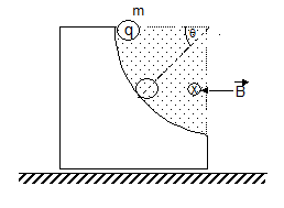
Solution:
Fm = qvB, and directed radially outward.
 \(\because \) N - mg sin q + qvB = \(\frac{m{{v}^{2}}}{R}\)
Þ N = \(\frac{m{{v}^{2}}}{R}+mg\sin \theta -qvB\)
Hence at q = p/2
\(\begin{align} & \Rightarrow {{N}_{\max }}=\frac{2mgR}{R}+mg-qB\sqrt{2gR} \\ & =3mg-qB\sqrt{2gR} \\ \end{align}\)
2. A uniform magnetic field of 30 mT exists in the + X direction. A particle of charge + e and mass 1.67 × 10⁻²⁷ kg is projected through the field in the + Y direction with a speed of 4.8 × 10⁶ m/s. Find the force if the particle were negatively charged and Describe the nature of path followed by the particle in both the cases.
Solution:
If the particle were negatively charged, the magnitude of the force will be the same but the direction will be along (+ z) direction
As v ^ B, the path described is a circle
R = \(\frac{\text{mv}}{\text{qB}}\) = (1.67 × 10⁻²⁷) . (4.8 × 10⁶) / (1.6 × 10⁻¹⁹) . (30 × 10-3)
= 1.67m.
1. A uniform magnetic field of 30 mT exists in the + X direction. A particle of charge + e and mass 1.67 × 10⁻²⁷ kg is projected through the field in the + Y direction with a speed of 4.8 × 10⁶ m/s. Find the force on the charged particle in magnitude and direction.
Solution:
Force acting on a charge particle moving in the magnetic field
\(\vec{F}=q(\vec{v}\times \vec{B}\))
Magnetic field \(\vec{B}\) = 30(mT)

Velocity of the charge particle \(\vec{v}\) = 4.8 ´ 106 (m/s)
\(\vec{F}=1.6\times {{10}^{-19}}[(4.8\times {{10}^{6}}\hat{j})\times (30\times {{10}^{-3}})(\hat{i})\)
\(\vec{F}=230.4\times {{10}^{-16}}(-k\hat{)}\)N.
2. A particle having mass m, charge q and velocity v passes through an electromagnetic field undeviated. If the electric field is E0, what we can say about the magnetic field?
Solution:
Since the particle passes through the field undeviated net force on it must be zero.
i.e. \(q\left[ {{E}_{0}}\ \hat{j}+v\hat{i}\times \vec{B} \right]\ =\ 0\)
At this point one may be tempted to directly take the direction of \(\vec{B}\) along z-axis to satisfy the equation. But that way we will not get a general solution to the problem. For general solution one must proceed as follows-
\(q\left[ {{E}_{0}}\ \hat{j}+v\hat{i}\times \left( {{B}_{x}}\ \hat{i}+{{B}_{y}}\ \hat{j}+{{B}_{z}}\ \hat{k} \right)\ \right]\ =\ 0\)
Þ \({{E}_{0}}\ \hat{j}\ +v\ {{B}_{y}}\ \hat{k}-v\ {{B}_{z}}\ \hat{j}\ =\ 0\)
Þ \(\left( {{E}_{0}}-v\ {{B}_{z}} \right)\ \hat{j}\ +v\ {{B}_{y}}\ \hat{k}\ =\ 0\)
Þ \({{B}_{z}}\ =\ \frac{{{E}_{0}}}{v},\ \ \ \ {{B}_{y}}\ =\ 0\)
Here, with the given information we can only find y and z components of the magnetic field.
The x component can have any value.

1. An electron gun G emits electrons of
energy 2keV travelling in the positive x
direction. The electrons are required to hit
the spot S where GS = 0.1 m, and the line
GS makes an angle 60o with the x - axis, as
shown. A uniform magnetic field B parallel
to GS exists in the region outside the
electron gun. Find the minimum value of B
needed to make the electrons hit S.
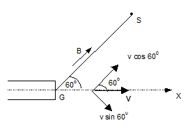
Solution:
Let the electron gun emit the electrons with initial velocity along x - axis.
Then, \(\frac{1}{2}m{{v}^{2}}\) = eV v = \(\sqrt{\frac{2eV}{m}}\)
Now the component of velocity of the electron beam along the direction of the magnetic field B is v|| and that ^ to B is v^
v|| = vcos q, v^= Vsinq |where q = 60°|
GS = n ´ pitch
Where n = 1, 2,…….
Þ GS = \(n\frac{2\pi m}{qB}\)vcosq Þ B = \(\frac{n2\pi m}{q.GS}\).vcosq
Where v = \(\sqrt{\frac{2eV}{m}}\)
For B to be minimum n should be 1
Substituting the values B = 4.7 ´ 10-3 T
2. A particle with charge +q and mass m, moving
under the influence of a uniform electric field E
and a uniform magnetic field B
 , follows a
 trajectory from P to Q as shown. The velocities at
P and Q are v
and –2v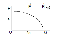
Solution:
In going from P to Q increase in kinetic energy
= \(\frac{1}{2}m{{(2v)}^{2}}\ -\ \frac{1}{2}m{{v}^{2}}=\frac{1}{2}\ m(3{{v}^{2}})\) = work done by electric field.
or \(\frac{3}{2}m{{v}^{2}}\ =Eq\times 2a\) or \(E\ =\ \frac{3}{4}\left( \frac{m{{v}^{2}}}{qa} \right)\)
The rate of work done by E at P = force due to E ´ velocity.
= \((qE)v=qv\left[ \frac{3}{4}\,\left( \frac{m{{v}^{2}}}{qa} \right) \right]\,=\ \frac{3}{4}\ \left( \frac{m{{v}^{3}}}{a} \right)\)
At q, \(\vec{v}\) is perpendicular to \(\vec{E}\) and \(\vec{B}\), and no work is done by either field.
-
MAGNETISM
When a charged particle having charge 'q' is projected into a magnetic field, it experiences a magnetic force which is given by the expression
\(\vec{F}=q\left( \vec{v}\times \vec{B} \right)\)
Here \(\vec{v}\) = velocity of the particle and
\(\vec{B}\) = magnetic field
Cases of Projection:
Case I : If velocity of charge particle v→ is parallel to B→ then -
F = q V B Sin 0o ⇒ F = 0
Case II: If a charge enters a magnetic field at right angle to it, it moves in a circular path due to magnetic force which acts as a centripetal force.
\({{F}_{B}}\to =\frac{m{{V}^{2}}}{r}\)
As we know –
FB = qVB→
Put the value of FB →
\(\therefore \text{ }qVB\text{ }=\frac{m{{V}^{2}}}{r}\)
We can derive multiple relations from the above equation.
Velocity of charge:
\(V=\frac{qBr}{m}\)
Observation: As magnetic field increases the velocity of charge increases.
Radius of circular path:
\(r=\frac{mV}{qB}\)
Observation: To maintain the radius of circular path, as the magnetic field increases the velocity should also increase.
Angular velocity:
\(\begin{align} & V=\frac{qBr}{m}\Rightarrow \text{ }r\omega \text{ }=\frac{qBr}{m} \\ & \therefore \text{ }\omega \text{ }=\frac{qB}{m} \\ \end{align}\)
q/m is known as specific charge.
Observation: Angular velocity depends upon the specific charge and magnetic field.
Time period of rotation:
\(\begin{align} & \omega \text{ }=\frac{2\pi }{T} \\ & \therefore \text{ }T\text{ }=~\frac{2\pi m}{qB} \\ \end{align}\)
Observation: As the magnetic field increases, the angular velocity increases and time period of rotation decreases.
Frequency:
\(\begin{align} & v=\frac{1}{T} \\ & \therefore \text{ }v\text{ }=\frac{qB}{2\pi m} \\ \end{align}\)
Observation: As the time period of rotation increases, the frequency of rotation decreases.
Kinetic energy of the rotating charge:
\(\begin{align} & K.E=\frac{1}{2}m{{v}^{2}} \\ & \therefore \text{ K}\text{.E}=\frac{{{q}^{2}}{{B}^{2}}{{r}^{2}}}{2m} \\ \end{align}\)
1. Moving charge experiences magnetic force because of
Solution:
Magnetic field
2. When charged particle is projected opposite to direction of magnetic field, it experiences force equal to
Solution:
zero
1. In the figure a charged sphere of mass m
and charge q starts sliding from rest on a
vertical fixed circular track of radius R
from the position shown. There exists a
uniform and constant horizontal magnetic
field of induction B. The maximum force
exerted by the track on the sphere is
Solution:
Fm = qvB, and directed radially outward.
\(\because \) N - mg sin q + qvB = \(\frac{m{{v}^{2}}}{R}\)Þ N = \(\frac{m{{v}^{2}}}{R}+mg\sin \theta -qvB\)
Hence at q = p/2
\(\begin{align} & \Rightarrow {{N}_{\max }}=\frac{2mgR}{R}+mg-qB\sqrt{2gR} \\ & =3mg-qB\sqrt{2gR} \\ \end{align}\)
2. A uniform magnetic field of 30 mT exists in the + X direction. A particle of charge + e and mass 1.67 × 10⁻²⁷ kg is projected through the field in the + Y direction with a speed of 4.8 × 10⁶ m/s. Find the force if the particle were negatively charged and Describe the nature of path followed by the particle in both the cases.
Solution:
If the particle were negatively charged, the magnitude of the force will be the same but the direction will be along (+ z) direction
As v ^ B, the path described is a circle
R = \(\frac{\text{mv}}{\text{qB}}\) = (1.67 × 10⁻²⁷) . (4.8 × 10⁶) / (1.6 × 10⁻¹⁹) . (30 × 10-3)
= 1.67m.1. A uniform magnetic field of 30 mT exists in the + X direction. A particle of charge + e and mass 1.67 × 10⁻²⁷ kg is projected through the field in the + Y direction with a speed of 4.8 × 10⁶ m/s. Find the force on the charged particle in magnitude and direction.
Solution:
Force acting on a charge particle moving in the magnetic field
\(\vec{F}=q(\vec{v}\times \vec{B}\))
Magnetic field \(\vec{B}\) = 30(mT)
Velocity of the charge particle \(\vec{v}\) = 4.8 ´ 106 (m/s)
\(\vec{F}=1.6\times {{10}^{-19}}[(4.8\times {{10}^{6}}\hat{j})\times (30\times {{10}^{-3}})(\hat{i})\)
\(\vec{F}=230.4\times {{10}^{-16}}(-k\hat{)}\)N.
2. A particle having mass m, charge q and velocity v passes through an electromagnetic field undeviated. If the electric field is E0, what we can say about the magnetic field?
Solution:
Since the particle passes through the field undeviated net force on it must be zero.
i.e. \(q\left[ {{E}_{0}}\ \hat{j}+v\hat{i}\times \vec{B} \right]\ =\ 0\)
At this point one may be tempted to directly take the direction of \(\vec{B}\) along z-axis to satisfy the equation. But that way we will not get a general solution to the problem. For general solution one must proceed as follows-
\(q\left[ {{E}_{0}}\ \hat{j}+v\hat{i}\times \left( {{B}_{x}}\ \hat{i}+{{B}_{y}}\ \hat{j}+{{B}_{z}}\ \hat{k} \right)\ \right]\ =\ 0\)
Þ \({{E}_{0}}\ \hat{j}\ +v\ {{B}_{y}}\ \hat{k}-v\ {{B}_{z}}\ \hat{j}\ =\ 0\)
Þ \(\left( {{E}_{0}}-v\ {{B}_{z}} \right)\ \hat{j}\ +v\ {{B}_{y}}\ \hat{k}\ =\ 0\)
Þ \({{B}_{z}}\ =\ \frac{{{E}_{0}}}{v},\ \ \ \ {{B}_{y}}\ =\ 0\)
Here, with the given information we can only find y and z components of the magnetic field.
The x component can have any value.
1. An electron gun G emits electrons of
energy 2keV travelling in the positive x
direction. The electrons are required to hit
the spot S where GS = 0.1 m, and the line
GS makes an angle 60o with the x - axis, as
shown. A uniform magnetic field B parallel
to GS exists in the region outside the
electron gun. Find the minimum value of B
needed to make the electrons hit S.
Solution:
Let the electron gun emit the electrons with initial velocity along x - axis.
Then, \(\frac{1}{2}m{{v}^{2}}\) = eV v = \(\sqrt{\frac{2eV}{m}}\)
Now the component of velocity of the electron beam along the direction of the magnetic field B is v|| and that ^ to B is v^
v|| = vcos q, v^= Vsinq |where q = 60°|
GS = n ´ pitch
Where n = 1, 2,…….
Þ GS = \(n\frac{2\pi m}{qB}\)vcosq Þ B = \(\frac{n2\pi m}{q.GS}\).vcosq
Where v = \(\sqrt{\frac{2eV}{m}}\)
For B to be minimum n should be 1
Substituting the values B = 4.7 ´ 10-3 T
2. A particle with charge +q and mass m, moving
under the influence of a uniform electric field E
and a uniform magnetic field B
, follows a trajectory from P to Q as shown. The velocities at
P and Q are v
and –2vSolution:
In going from P to Q increase in kinetic energy
= \(\frac{1}{2}m{{(2v)}^{2}}\ -\ \frac{1}{2}m{{v}^{2}}=\frac{1}{2}\ m(3{{v}^{2}})\) = work done by electric field.
or \(\frac{3}{2}m{{v}^{2}}\ =Eq\times 2a\) or \(E\ =\ \frac{3}{4}\left( \frac{m{{v}^{2}}}{qa} \right)\)
The rate of work done by E at P = force due to E ´ velocity.
= \((qE)v=qv\left[ \frac{3}{4}\,\left( \frac{m{{v}^{2}}}{qa} \right) \right]\,=\ \frac{3}{4}\ \left( \frac{m{{v}^{3}}}{a} \right)\)
At q, \(\vec{v}\) is perpendicular to \(\vec{E}\) and \(\vec{B}\), and no work is done by either field.
-
MAGNETISM

Consider a particle of mass m , charge q , moving horizontally with velocity u , as shown in the figure. The charge enters a region between two parallel plates (length L), where an electric field E , as shown exists. Since, there is no horizontal force on the particle , the horizontal component of velocity does not change ,
vx = u at all times . The time spent by the particle in the field region is t = L/u
During this time, the particle experiences a vertical force Fy = qE . Due to this force acceleration in
Y-direction is ay = qE/m . In time t , the velocity acquired in Y-direction isvy = ayt
vy = qEL/mu
The angle θ , at which the particle emerges out of the field (figure) is
tan θ = vy/vx
The velocity with which the particle comes out of the field is
\(v=\sqrt{{{v}_{x}}^{2}+{{v}_{y}}^{2}}=\sqrt{{{u}^{2}}+{{\left( \frac{qEL}{mu} \right)}^{2}}}\)
The path of the particle in this case is parabolic this can be seen as follows. In any time t, the distances traveled by the particle in x, and y direction are
\(y=\frac{1}{2}{{a}_{y}}{{t}^{2}}=\frac{qE}{2m}{{t}^{2}},x=ut\)
eliminating t , we get
\(y=\left( \frac{qE}{2m{{u}^{2}}} \right){{x}^{2}}\)
y ∝ x2
The path is a parabola.

1. Two electrons are placed at a certain distance between each other? The force between them is:
Solution:
Two electrons have negative charge, therefore the force is repulsion.
2. A negatively charged particle is placed in a uniform electric field directed from South to North. In which direction will the particle move after it is released?
Solution:
A negatively charged particle placed into the electric field will move in the direction opposite to the field. Therefore, it is South.

1. Find force between a proton and an electron placed at the distance 1 µm.
Solution:
The force between two oppositely charged particles is attraction and its value is
\(F=k\frac{{{q}_{1}}{{q}_{2}}}{{{r}^{2}}}=8.99\times {{10}^{9}}\frac{1.6\times {{10}^{-19}}\times 1.6\times {{10}^{-19}}}{{{({{10}^{-6}})}^{2}}}=2.3\times {{10}^{-16}}\)
2. A negatively charged particle accelerates from East to West in a uniform electric field. What are the direction and the value of the electric field if the particle has charge q=3 µC, mass m=1 mg, and if the value of its acceleration is 3 mm/s2 ? Select the closest answer:
Solution:
If the particle is moving from East to West and it is negatively charged, the electric field is opposite to the particle movement, therefore it is directed from West.to East. Its value can be found from the second Newton law:
qE = ma and it is given by E = ma/q = \({{10}^{-6}}\times 3\times {{10}^{-3}}/3\times {{10}^{-6}}=0.001\)

1. A particle with a specific charge s starts from rest in a region where the electric field has a constant direction, but whose magnitude increase linearly with time. The particle acquires a velocity v in time t.
Solution:
E = at (a = constant ) F = QE
a = F/m = QE/m = Es = ast.
\ a = \(\frac{dv}{dt}\)= ast
or v = \(\frac{1}{2}\) as t2
\ v µ s and t2

1. An electron moves straight inside a charged parallel plate capacitor of uniform surface charge density s. The space between the plates is filled with constant magnetic field of induction \(\vec{B}\). Neglect gravity, the time of straight line motion of the electron in the capacitor is
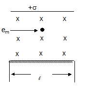
Solution:
The net electric field
\(E={{\vec{E}}_{1}}+{{\vec{E}}_{2}}\)
\(\Rightarrow \,\,E=\frac{\sigma }{2{{\varepsilon }_{o}}}+\frac{\sigma }{2{{\varepsilon }_{o}}}=\frac{\sigma }{{{\varepsilon }_{o}}}\)
The net force acting on the electron is zero because it moves with constant velocity
\(\Rightarrow \,\,{{\vec{F}}_{net}}={{\vec{F}}_{e}}+{{\vec{F}}_{m}}=0\) \(\Rightarrow \,\,\left| {{{\vec{F}}}_{e}} \right|=\left| {{{\vec{F}}}_{m}} \right|\)
Þ eE = evB \(\Rightarrow \,\,v=\frac{E}{B}=\frac{\sigma }{{{\varepsilon }_{o}}B}\)
\ The time of motion in side the capacitor
\(=t=\frac{\ell }{v}=\frac{{{\varepsilon }_{o}}\ell B}{\sigma }\).
-
MAGNETISM
Consider a particle of mass m , charge q , moving horizontally with velocity u , as shown in the figure. The charge enters a region between two parallel plates (length L), where an electric field E , as shown exists. Since, there is no horizontal force on the particle , the horizontal component of velocity does not change ,
vx = u at all times . The time spent by the particle in the field region is t = L/uDuring this time, the particle experiences a vertical force Fy = qE . Due to this force acceleration in
Y-direction is ay = qE/m . In time t , the velocity acquired in Y-direction isvy = ayt
vy = qEL/mu
The angle θ , at which the particle emerges out of the field (figure) is
tan θ = vy/vx
The velocity with which the particle comes out of the field is
\(v=\sqrt{{{v}_{x}}^{2}+{{v}_{y}}^{2}}=\sqrt{{{u}^{2}}+{{\left( \frac{qEL}{mu} \right)}^{2}}}\)
The path of the particle in this case is parabolic this can be seen as follows. In any time t, the distances traveled by the particle in x, and y direction are
\(y=\frac{1}{2}{{a}_{y}}{{t}^{2}}=\frac{qE}{2m}{{t}^{2}},x=ut\)
eliminating t , we get
\(y=\left( \frac{qE}{2m{{u}^{2}}} \right){{x}^{2}}\)
y ∝ x2
The path is a parabola.
1. Two electrons are placed at a certain distance between each other? The force between them is:
Solution:
Two electrons have negative charge, therefore the force is repulsion.
2. A negatively charged particle is placed in a uniform electric field directed from South to North. In which direction will the particle move after it is released?
Solution:
A negatively charged particle placed into the electric field will move in the direction opposite to the field. Therefore, it is South.
1. Find force between a proton and an electron placed at the distance 1 µm.
Solution:
The force between two oppositely charged particles is attraction and its value is
\(F=k\frac{{{q}_{1}}{{q}_{2}}}{{{r}^{2}}}=8.99\times {{10}^{9}}\frac{1.6\times {{10}^{-19}}\times 1.6\times {{10}^{-19}}}{{{({{10}^{-6}})}^{2}}}=2.3\times {{10}^{-16}}\)
2. A negatively charged particle accelerates from East to West in a uniform electric field. What are the direction and the value of the electric field if the particle has charge q=3 µC, mass m=1 mg, and if the value of its acceleration is 3 mm/s2 ? Select the closest answer:
Solution:
If the particle is moving from East to West and it is negatively charged, the electric field is opposite to the particle movement, therefore it is directed from West.to East. Its value can be found from the second Newton law:
qE = ma and it is given by E = ma/q = \({{10}^{-6}}\times 3\times {{10}^{-3}}/3\times {{10}^{-6}}=0.001\)
1. A particle with a specific charge s starts from rest in a region where the electric field has a constant direction, but whose magnitude increase linearly with time. The particle acquires a velocity v in time t.
Solution:
E = at (a = constant ) F = QE
a = F/m = QE/m = Es = ast.
\ a = \(\frac{dv}{dt}\)= ast
or v = \(\frac{1}{2}\) as t2
\ v µ s and t2
1. An electron moves straight inside a charged parallel plate capacitor of uniform surface charge density s. The space between the plates is filled with constant magnetic field of induction \(\vec{B}\). Neglect gravity, the time of straight line motion of the electron in the capacitor is
Solution:
The net electric field
\(E={{\vec{E}}_{1}}+{{\vec{E}}_{2}}\)
\(\Rightarrow \,\,E=\frac{\sigma }{2{{\varepsilon }_{o}}}+\frac{\sigma }{2{{\varepsilon }_{o}}}=\frac{\sigma }{{{\varepsilon }_{o}}}\)
The net force acting on the electron is zero because it moves with constant velocity
\(\Rightarrow \,\,{{\vec{F}}_{net}}={{\vec{F}}_{e}}+{{\vec{F}}_{m}}=0\) \(\Rightarrow \,\,\left| {{{\vec{F}}}_{e}} \right|=\left| {{{\vec{F}}}_{m}} \right|\)
Þ eE = evB \(\Rightarrow \,\,v=\frac{E}{B}=\frac{\sigma }{{{\varepsilon }_{o}}B}\)
\ The time of motion in side the capacitor
\(=t=\frac{\ell }{v}=\frac{{{\varepsilon }_{o}}\ell B}{\sigma }\).
-
MAGNETISM

A current carrying conductor is itself formed by moving charges. Hence, when a current carrying conductor is placed in a magnetic field it experiences a force.
To study the force on a current-carrying straight conductor in a magnetic field and to verify that the motion of the conductor is according to Fleming’s left-hand rule.
A current carrying conductor placed in a magnetic field experiences a force. If the direction of the field and that of current are mutually perpendicular to each other, then the force acting on the conductor will be perpendicular to both and that can be determined using the Fleming’s left-hand rule. When current establishes in the conductor, it gets displaced which verifies the existence of a force on the conductor.
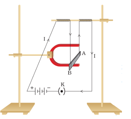
A current-carrying rod, AB, experiences a force perpendicular to its length and the magnetic field
As \(\vec{F}=q\left( \vec{v}\times \vec{B} \right)\)
We can say
\(d\vec{F}=dq[\vec{v}\times \vec{B}]\)
or \(d\vec{F}=dq\left[ \frac{d\vec{\ell }}{dt}\times \vec{B} \right]=\frac{dq}{dt}\left[ d\vec{\ell }\times \vec{B} \right]\)
Þ \(d\vec{F}=I\left( d\vec{\ell }\times \vec{B} \right)\)
FLEMING'S LEFT- HAND RULE :
In the special case of straight wire of length L in a uniform magnetic field B,
\(\vec{F}=I\left( \vec{\ell }\times \vec{B} \right)\)
The direction of the force \(\vec{F}=I\left( \vec{\ell }\times \vec{B} \right)\) is given by the Fleming's left hand rule.
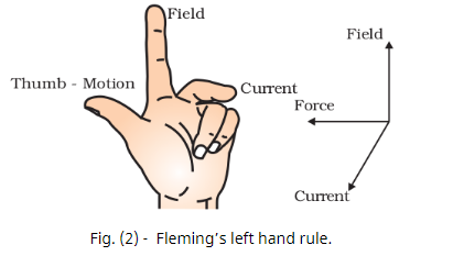
old the thumb and the first two fingers of your left hand mutually at right angles to each other as shown in Fig. (2). Then if the Forefinger points in the direction of the Field, and the second finger in the direction of the Current, the thumb will point in the direction of Force.

1. The lines of force due to the earth's horizontal magnetic field at a given place are
Solution:
Parallel and straight
2. Points A and B are situated along the extended axis of a 2cm long bar magnet at distances 'x' and 'dx' cm respectively from the pole nearer to the point. The ratio of the magnetic fields at A and B will be
Solution:
d3 : 1 approximately

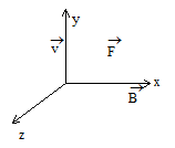
1. A long, rigid wire lying along the y-axis carries a 5.0-A current flowing in the positive y-direction. If a constant magnetic field of magnitude 0.30 T is directed along the positive x-axis, what is the magnetic force per unit length on the wire?
Solution:
We start with the general formula for the magnetic force on a wire. We are looking for the force per unit length, so we divide by the length to bring it to the left- hand side. We also set
\(\begin{align} & F=IlB~sin~\theta \\ & \frac{F}{l}=(5.0~A)(0.30~T) \\ & \frac{F}{l}=1.5N/m \\ \end{align}\)
2. A long, rigid wire lying along the y-axis carries a 5.0-A current flowing in the positive y-direction. If a constant magnetic field of 0.30 T is directed 30 degrees from the +x-axis towards the +y-axis, what is the magnetic force per unit length on the wire?
Solution:
The current times length and the magnetic field are written in unit vector notation. Then, we take the cross product to find the force:
\(\begin{align} & \vec{F}=I\vec{l}\times \vec{B}=(5.0A)l\hat{j}\times (0.30Tcos({{30}^{o}})\hat{i} \\ & \vec{F}/l=-1.30\hat{k}N/m \\ \end{align}\)
This large magnetic field creates a significant force on a small length of wire. As the angle of the magnetic field becomes more closely aligned to the current in the wire, there is less of a force on it.

1. The magnetic moment of an electron orbiting in a circular orbit of radius r with a speed v is equal to :
Solution:
Magnetic moment m = niA
Where n = number of turns of the current loop
I = current; Since the orbiting electron behaves as a current loop of current i
we can write \(i=\frac{e}{T}=\frac{e}{\frac{2\pi r}{v}}=\frac{ev}{2\pi r}\)
A = area of the loop = pr2
\(\Rightarrow \,\,\mu =\left( 1 \right)\,\,\left( \frac{ev}{2\pi r} \right)\,\left( \pi {{r}^{2}} \right)\) Þ m = \(\frac{evr}{2}\)
2. A wire of length 5.0 cm carries a current of 3.0 A; kept in an external uniform magnetic field of magnitude 10-3 Wbm-2. Calculate the magnetic force exerted on the wire, if the wire is inclined at 30° with \(\vec{B}\)
Solution:
The force is given by the vector relation
\(\vec{F}=i\vec{\ell }\times \vec{B}\)
\ F = i\(\ell \)B sinq where q is the angle between \(\vec{l}\,and\,\vec{B}\)
F = (3.0A) ´ (5 ´ 10-2 m) ´ (10-3 Wbm-2) ´ 0.5
= 7.5 ´ 10-5 N
The direction of this force is perpendicular to the plane which contains both \(\vec{l}\,and\,\vec{B}\)

1. Show that the force on a straight wire between a and b of the figure given is the same as the force on a wire of arbitrary shape between the same two points when they carry the same current from a to b and placed in the same magnetic field.
Solution:
Force on the straight conductor
\(\vec{F}\) = il Bsin 90 \(\hat{j}\) = il B\(\hat{j}\)
Where ab = l, Now consider an element Dl of the curved wire, The force on the element
= DF = iDlB sin 90 = i DlB
The direction of the force is at right angles to the element.
Then, \(\Delta \,\vec{F}\) = iDl B cosq \(\hat{i}\) + iDl B sinq \(\hat{j}\)
Hence net force \(\vec{F}\) =\(\Delta \,\vec{F}\) = iB \(\left( \sum{\Delta \ell \,\cos \theta } \right)\,\hat{i}\)+ iB \(\left( \sum{\Delta \ell \,\sin \theta } \right)\,\hat{j}\)
\(\sum{\Delta \ell \,\cos \theta }\) = sum of projection of Dl’s on ab = l and \(\sum{\Delta \ell \,\sin \theta }\,\,=\,\,0\)
Hence net force on \(\vec{F}\) = il B\(\hat{j}\), which is same the force on the straight-line conductor ab.
2. In the figure shown the magnetic field at the point P is
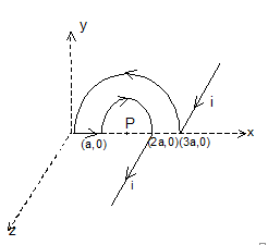
Solution:
\({{\vec{B}}_{p}}={{\left( {{{\vec{B}}}_{1}} \right)}_{p}}+{{\left( {{{\vec{B}}}_{2}} \right)}_{p}}+{{\left( {{{\vec{B}}}_{3}} \right)}_{p}}+{{\left( {{{\vec{B}}}_{4}} \right)}_{p}}+{{\left( {{{\vec{B}}}_{5}} \right)}_{p}}\)
where
\({{\left( {{{\vec{B}}}_{1}} \right)}_{p}}=\frac{{{\mu }_{o}}i}{4\pi \left( \frac{3a}{2} \right)}\,\,(-\hat{j})\) (semi-infinite wire)
\({{\left( {{{\vec{B}}}_{2}} \right)}_{p}}=\frac{{{\mu }_{o}}i}{4\,\left( \frac{3a}{2} \right)}\,\,(+\hat{k})\)
\({{\left( {{{\vec{B}}}_{3}} \right)}_{p}}=0\)
\({{\left( {{{\vec{B}}}_{4}} \right)}_{p}}=\frac{{{\mu }_{o}}i}{4\,\left( \frac{a}{2} \right)}\,\,(-\hat{k})\)
\({{\left( {{{\vec{B}}}_{5}} \right)}_{p}}=\frac{{{\mu }_{o}}i}{4\,\pi \,\left( \frac{a}{2} \right)}\,\,(-\hat{j})\)
\(\Rightarrow \,\,{{\vec{B}}_{p}}=\frac{{{\mu }_{o}}i}{a}\,\left[ -\left( \frac{1}{3\pi }+\frac{1}{\pi } \right)\,\hat{j}-\left( 1-\frac{1}{3} \right)\,\hat{k} \right]\)
\(\Rightarrow \,\,{{\vec{B}}_{p}}=\frac{2{{\mu }_{o}}i}{3a}\,\left[ \frac{2}{\pi }j+\hat{k} \right]\)
\(\Rightarrow \,\,{{\vec{B}}_{p}}=\frac{{{\mu }_{o}}i}{3\pi \,a}\,\sqrt{4\,+\,{{\pi }^{2}}}\)
-
MAGNETISM
A current carrying conductor is itself formed by moving charges. Hence, when a current carrying conductor is placed in a magnetic field it experiences a force.
To study the force on a current-carrying straight conductor in a magnetic field and to verify that the motion of the conductor is according to Fleming’s left-hand rule.
A current carrying conductor placed in a magnetic field experiences a force. If the direction of the field and that of current are mutually perpendicular to each other, then the force acting on the conductor will be perpendicular to both and that can be determined using the Fleming’s left-hand rule. When current establishes in the conductor, it gets displaced which verifies the existence of a force on the conductor.
A current-carrying rod, AB, experiences a force perpendicular to its length and the magnetic field
As \(\vec{F}=q\left( \vec{v}\times \vec{B} \right)\)
We can say
\(d\vec{F}=dq[\vec{v}\times \vec{B}]\)
or \(d\vec{F}=dq\left[ \frac{d\vec{\ell }}{dt}\times \vec{B} \right]=\frac{dq}{dt}\left[ d\vec{\ell }\times \vec{B} \right]\)
Þ \(d\vec{F}=I\left( d\vec{\ell }\times \vec{B} \right)\)
FLEMING'S LEFT- HAND RULE :
In the special case of straight wire of length L in a uniform magnetic field B,
\(\vec{F}=I\left( \vec{\ell }\times \vec{B} \right)\)
The direction of the force \(\vec{F}=I\left( \vec{\ell }\times \vec{B} \right)\) is given by the Fleming's left hand rule.
old the thumb and the first two fingers of your left hand mutually at right angles to each other as shown in Fig. (2). Then if the Forefinger points in the direction of the Field, and the second finger in the direction of the Current, the thumb will point in the direction of Force.
1. The lines of force due to the earth's horizontal magnetic field at a given place are
Solution:
Parallel and straight
2. Points A and B are situated along the extended axis of a 2cm long bar magnet at distances 'x' and 'dx' cm respectively from the pole nearer to the point. The ratio of the magnetic fields at A and B will be
Solution:
d3 : 1 approximately
1. A long, rigid wire lying along the y-axis carries a 5.0-A current flowing in the positive y-direction. If a constant magnetic field of magnitude 0.30 T is directed along the positive x-axis, what is the magnetic force per unit length on the wire?
Solution:
We start with the general formula for the magnetic force on a wire. We are looking for the force per unit length, so we divide by the length to bring it to the left- hand side. We also set
\(\begin{align} & F=IlB~sin~\theta \\ & \frac{F}{l}=(5.0~A)(0.30~T) \\ & \frac{F}{l}=1.5N/m \\ \end{align}\)
2. A long, rigid wire lying along the y-axis carries a 5.0-A current flowing in the positive y-direction. If a constant magnetic field of 0.30 T is directed 30 degrees from the +x-axis towards the +y-axis, what is the magnetic force per unit length on the wire?
Solution:
The current times length and the magnetic field are written in unit vector notation. Then, we take the cross product to find the force:
\(\begin{align} & \vec{F}=I\vec{l}\times \vec{B}=(5.0A)l\hat{j}\times (0.30Tcos({{30}^{o}})\hat{i} \\ & \vec{F}/l=-1.30\hat{k}N/m \\ \end{align}\)
This large magnetic field creates a significant force on a small length of wire. As the angle of the magnetic field becomes more closely aligned to the current in the wire, there is less of a force on it.
1. The magnetic moment of an electron orbiting in a circular orbit of radius r with a speed v is equal to :
Solution:
Magnetic moment m = niA
Where n = number of turns of the current loop
I = current; Since the orbiting electron behaves as a current loop of current i
we can write \(i=\frac{e}{T}=\frac{e}{\frac{2\pi r}{v}}=\frac{ev}{2\pi r}\)
A = area of the loop = pr2
\(\Rightarrow \,\,\mu =\left( 1 \right)\,\,\left( \frac{ev}{2\pi r} \right)\,\left( \pi {{r}^{2}} \right)\) Þ m = \(\frac{evr}{2}\)
2. A wire of length 5.0 cm carries a current of 3.0 A; kept in an external uniform magnetic field of magnitude 10-3 Wbm-2. Calculate the magnetic force exerted on the wire, if the wire is inclined at 30° with \(\vec{B}\)
Solution:
The force is given by the vector relation
\(\vec{F}=i\vec{\ell }\times \vec{B}\)
\ F = i\(\ell \)B sinq where q is the angle between \(\vec{l}\,and\,\vec{B}\)
F = (3.0A) ´ (5 ´ 10-2 m) ´ (10-3 Wbm-2) ´ 0.5
= 7.5 ´ 10-5 N
The direction of this force is perpendicular to the plane which contains both \(\vec{l}\,and\,\vec{B}\)
1. Show that the force on a straight wire between a and b of the figure given is the same as the force on a wire of arbitrary shape between the same two points when they carry the same current from a to b and placed in the same magnetic field.
Solution:
Force on the straight conductor
\(\vec{F}\) = il Bsin 90 \(\hat{j}\) = il B\(\hat{j}\)
Where ab = l, Now consider an element Dl of the curved wire, The force on the element
= DF = iDlB sin 90 = i DlB
The direction of the force is at right angles to the element.
Then, \(\Delta \,\vec{F}\) = iDl B cosq \(\hat{i}\) + iDl B sinq \(\hat{j}\)
Hence net force \(\vec{F}\) =\(\Delta \,\vec{F}\) = iB \(\left( \sum{\Delta \ell \,\cos \theta } \right)\,\hat{i}\)+ iB \(\left( \sum{\Delta \ell \,\sin \theta } \right)\,\hat{j}\)
\(\sum{\Delta \ell \,\cos \theta }\) = sum of projection of Dl’s on ab = l and \(\sum{\Delta \ell \,\sin \theta }\,\,=\,\,0\)
Hence net force on \(\vec{F}\) = il B\(\hat{j}\), which is same the force on the straight-line conductor ab.
2. In the figure shown the magnetic field at the point P is
Solution:
\({{\vec{B}}_{p}}={{\left( {{{\vec{B}}}_{1}} \right)}_{p}}+{{\left( {{{\vec{B}}}_{2}} \right)}_{p}}+{{\left( {{{\vec{B}}}_{3}} \right)}_{p}}+{{\left( {{{\vec{B}}}_{4}} \right)}_{p}}+{{\left( {{{\vec{B}}}_{5}} \right)}_{p}}\)
where
\({{\left( {{{\vec{B}}}_{1}} \right)}_{p}}=\frac{{{\mu }_{o}}i}{4\pi \left( \frac{3a}{2} \right)}\,\,(-\hat{j})\) (semi-infinite wire)
\({{\left( {{{\vec{B}}}_{2}} \right)}_{p}}=\frac{{{\mu }_{o}}i}{4\,\left( \frac{3a}{2} \right)}\,\,(+\hat{k})\)
\({{\left( {{{\vec{B}}}_{3}} \right)}_{p}}=0\)
\({{\left( {{{\vec{B}}}_{4}} \right)}_{p}}=\frac{{{\mu }_{o}}i}{4\,\left( \frac{a}{2} \right)}\,\,(-\hat{k})\)
\({{\left( {{{\vec{B}}}_{5}} \right)}_{p}}=\frac{{{\mu }_{o}}i}{4\,\pi \,\left( \frac{a}{2} \right)}\,\,(-\hat{j})\)
\(\Rightarrow \,\,{{\vec{B}}_{p}}=\frac{{{\mu }_{o}}i}{a}\,\left[ -\left( \frac{1}{3\pi }+\frac{1}{\pi } \right)\,\hat{j}-\left( 1-\frac{1}{3} \right)\,\hat{k} \right]\)
\(\Rightarrow \,\,{{\vec{B}}_{p}}=\frac{2{{\mu }_{o}}i}{3a}\,\left[ \frac{2}{\pi }j+\hat{k} \right]\)
\(\Rightarrow \,\,{{\vec{B}}_{p}}=\frac{{{\mu }_{o}}i}{3\pi \,a}\,\sqrt{4\,+\,{{\pi }^{2}}}\)
-
MAGNETISM

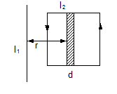
Two current carrying straight conductors placed near each other will exert (magnetic) forces on each other due to magnetic field of each other.
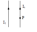
Let two infinite parallel wires carrying currents I1 and I2 are separated by a distance r.
If we take an arbitrary point. 'P' on the second wire, the angle a and b subtended by the other wire are :
a = 0 and b = 0.
\({{B}_{21}}=\,\,\,\,\frac{{{\mu }_{o}}{{I}_{1}}}{4\pi r}[\cos 0+\cos 0]\,\,=\frac{{{\mu }_{o}}{{I}_{1}}}{2\pi r}\)
\({{\overline{F}}_{21}}={{I}_{2}}\left( \vec{\ell }\,\,\times {{{\vec{B}}}_{1}} \right)\Rightarrow \,\,{{F}_{21}}=\frac{{{I}_{2}}{{\ell }_{2}}{{\mu }_{o}}{{I}_{1}}}{2\pi r}\)
\(\frac{{{F}_{21}}}{{{\ell }_{2}}}=\frac{{{\mu }_{o}}{{I}_{1}}{{I}_{2}}}{2\pi r}\,\,\,\,By\,\,\,symmetry\,\,\frac{{{F}_{12}}}{{{\ell }_{1}}}=\frac{{{\mu }_{o}}{{I}_{1}}{{I}_{2}}}{2\pi r}\)
Force per unit length \(=\frac{{{\mu }_{o}}{{I}_{1}}{{I}_{2}}}{2\pi r}\)
We note that wires carrying current in the same direction attract. (Verify using Fleming's left-hand rule)
Note − Parallel current carrying wires attract, and anti-parallel current carrying wires repel each other.
Example : Two very long parallel conductors are located at a distance of 0.75 cm from each other, perpendicular to the plane of the figure below. Conductor 1 is carrying a current of 6.5 A towards the picture plane. What current (magnitude and direction) must flow through conductor 2 to produce a zero magnetic field at point P?
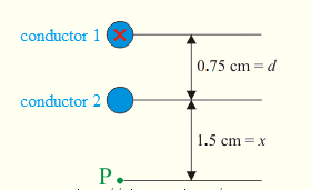
Solution:
x=1.5cmx=1.5cm
distance between point P and the nearer conductor (2)
d=0.75cmd=0.75cm
distance between the conductors
\({{I}_{1}}\) =6.5AI1=6.5A
current flowing through the first conductor
\({{I}_{2}}\) =?(A)I2=?(A)
current flowing through the second conductor
There is no need to convert distances from centimeters to meters because the length dimensions stand in a plain ratio in the numerator and the denominator of the fraction. Their units thus cancel out.
\({{I}_{2}}={{I}_{1}}\frac{x}{d+x}=6.5\frac{1.5}{0.75+1.5}A=4.3A\)
and it flows in the opposite direction than the current in conductor 1, which means that it flows towards us.
-
MAGNETISM
Two current carrying straight conductors placed near each other will exert (magnetic) forces on each other due to magnetic field of each other.
Let two infinite parallel wires carrying currents I1 and I2 are separated by a distance r.
If we take an arbitrary point. 'P' on the second wire, the angle a and b subtended by the other wire are :
a = 0 and b = 0.
\({{B}_{21}}=\,\,\,\,\frac{{{\mu }_{o}}{{I}_{1}}}{4\pi r}[\cos 0+\cos 0]\,\,=\frac{{{\mu }_{o}}{{I}_{1}}}{2\pi r}\)
\({{\overline{F}}_{21}}={{I}_{2}}\left( \vec{\ell }\,\,\times {{{\vec{B}}}_{1}} \right)\Rightarrow \,\,{{F}_{21}}=\frac{{{I}_{2}}{{\ell }_{2}}{{\mu }_{o}}{{I}_{1}}}{2\pi r}\)
\(\frac{{{F}_{21}}}{{{\ell }_{2}}}=\frac{{{\mu }_{o}}{{I}_{1}}{{I}_{2}}}{2\pi r}\,\,\,\,By\,\,\,symmetry\,\,\frac{{{F}_{12}}}{{{\ell }_{1}}}=\frac{{{\mu }_{o}}{{I}_{1}}{{I}_{2}}}{2\pi r}\)
Force per unit length \(=\frac{{{\mu }_{o}}{{I}_{1}}{{I}_{2}}}{2\pi r}\)
We note that wires carrying current in the same direction attract. (Verify using Fleming's left-hand rule)
Note − Parallel current carrying wires attract, and anti-parallel current carrying wires repel each other.
Example : Two very long parallel conductors are located at a distance of 0.75 cm from each other, perpendicular to the plane of the figure below. Conductor 1 is carrying a current of 6.5 A towards the picture plane. What current (magnitude and direction) must flow through conductor 2 to produce a zero magnetic field at point P?
Solution:
x=1.5cmx=1.5cm
distance between point P and the nearer conductor (2)
d=0.75cmd=0.75cm
distance between the conductors
\({{I}_{1}}\) =6.5AI1=6.5A
current flowing through the first conductor
\({{I}_{2}}\) =?(A)I2=?(A)
current flowing through the second conductor
There is no need to convert distances from centimeters to meters because the length dimensions stand in a plain ratio in the numerator and the denominator of the fraction. Their units thus cancel out.
\({{I}_{2}}={{I}_{1}}\frac{x}{d+x}=6.5\frac{1.5}{0.75+1.5}A=4.3A\)
and it flows in the opposite direction than the current in conductor 1, which means that it flows towards us.
-
MAGNETISM

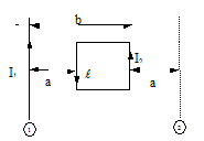
Case I:
When place of the loop is perpendicular to magnetic field \(\ell \)
Length of AB = DC =
And that of BC = AD = b
Forces experienced by all the sides are shown in the figure
\ Force on AB and DC are equal and opposite to the each other and that on BC and AD too.
Þ SF = 0
Since the line of action of the forces on AB and DC is same and also the line of action of the forces BC and AD is same, therefore torque is zero.
Case II:
When the plane of the loop is inclined to the magnetic field.
In this case again SF = 0
\ Lines of action of the forces on AB and DC are different, therefore this forms a couple and produces a torque. Side view of the loop is shown in the figure.
Torque = BIl(bsinq) = BI(lb)sinq
Þ BIAsinq.
If loop has N turns then
t = BNIA sin q
In vector form
\(\vec{\tau }=\vec{\mu }\times \vec{B}\), where, \(\vec{\mu }=NI\vec{A}\)Energy needed to rotate the loop through an angle dq is
dU = tdq
Þ DU = \(\int{dU}=\int\limits_{{{\theta }_{1}}}^{{{\theta }_{2}}}{\tau d\theta }=\int\limits_{{{\theta }_{1}}}^{{{\theta }_{2}}}{\mu B\sin \theta d\theta }\)
DU = mB(cosq1 - cosq2), if we choose at q1 such that at q = q1, U1 = 0
This is the energy stored in the loop.
U = -\({{\vec{\mu }}_{m}}.\vec{B}\)

1. A magnetic field is produced and directed along y-axis. A magnet is placed along y- axis. The direction of torque on the magnet is
Solution:
In the x-y plane
2. If a bar magnet of moment is suspended in a uniform magnetic field it is given an angular deflection, w.r.t equilibrium position. Then the restoring torque on the magnet is
Solution:
MB tan \(\theta \)

1.
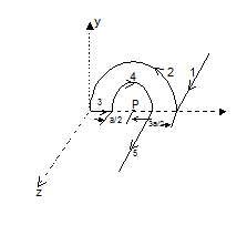
A wire loop carrying a current I is placed in the x-y plane as shown in fig. If an external uniform magnetic induction \(\vec{B}\,=B\hat{i}\) is applied, find the force and torque acting on the loop.
Solution:
As d\(\overrightarrow{\,F\,}\,\,=\,\,Id\,\overrightarrow{L\,}\,x\,\overrightarrow{\,B\,},\,\,\,so\,\,\,\overrightarrow{\,F\,}\,\,=\,\,\int_{{}}^{{}}{Id\overrightarrow{\,L\,}\,x\,\overrightarrow{\,B\,}}\)
As here I and \(\overrightarrow{B}\) are constant
\(\overrightarrow{F}\,=\,\,I\,\left[ \oint{d\overrightarrow{L}} \right]\,x\,\overrightarrow{B}\,\,=\,\,0\left[ as\,\,\oint{d\,\overrightarrow{L}\,\,=\,\,0} \right]\)
Further as area of coil,
\(\overrightarrow{S}\,\,=\,\,\left[ \frac{1}{3}\,\pi \,{{a}^{2}}\,\,-\,\,\frac{1}{2}\,.\,2a\,\sin {{60}^{0}}\,x\,a\,\cos {{60}^{0}} \right]\,\hat{k}\,\,=\,\,{{a}^{2}}\,\left[ \frac{\pi }{3}\,\,-\,\,\frac{\sqrt{3}}{4} \right]\hat{k}\)
so \(\overrightarrow{M}\) = \(I\,\overrightarrow{\,S\,}\,\,=\,\,I{{a}^{2}}\,\left[ \frac{\pi }{3}\,\,-\,\,\frac{\sqrt{3}}{4} \right]\,\hat{k}\)
and hence \(\overrightarrow{\tau }\,\,=\,\,\overrightarrow{M}\,\,x\,\,\overrightarrow{B}\,\,=\,\,I\,{{a}^{2}}B\,\left[ \frac{\pi }{3}\,\,-\,\,\frac{\sqrt{3}}{4} \right]\,\left( \hat{k}\,x\hat{i} \right)\,\,\)
i.e. \(\overrightarrow{\tau }\,\,=\,\,I{{a}^{2}}\,B\,\,\left[ \frac{\pi }{3}\,\,-\,\,\frac{\sqrt{3}}{4} \right]\,\hat{j}\,N-mas\,\left( \hat{k}\,x\hat{i}\,\,=\,\hat{j} \right)\)

1. The coil of a galvanometer has 500 turns and each turns has an average area 3 ´ 10-4 m2. Calculate the magnetic moment of the coil when a current of 0.5 A passes through it. If a torque of 1.5 Nm is required for this coil carrying same current to set it parallel to a magnetic field, calculate the strength of the magnetic field.
Solution:
The magnetic moment of a current loop
m = NI A = 500 x 0.5 x 3 x 10-4 = 0.075 Am2.
Also \(\vec{\tau }\,=\,\vec{\mu }\,x\,\vec{B}\,\,or\,\,\,|\vec{\tau }|\,\,=\,\,\mu \,B\,\sin \theta \)
Where q = angle between B and A
Here, q =900
\(\therefore \tau \,\,=\,\,\mu \,B\,\sin {{90}^{0}}\)
B = \(\frac{\tau }{\mu }\,\,=\,\,\frac{1.5}{0.075}\,\,=\,\,20\,T\)
2. The rectangular coil having 100 turns is turned in a uniform magnetic field of \(\frac{0.05}{\sqrt{2}}\,\,\hat{j}\) Tesla as shown in the figure. The torque acting on the loop
Solution:
The magnetic dipole moment of the current carrying coil is given by \(\vec{m}=NIA\hat{n}\)
= 100 ´ 0.5 ´ 0.08 ´ 0.04 î
= 1.6 ´ 10-2 Am2The torque acting on the coil is
\(\vec{\tau }=\vec{m}\times \vec{B}\)
\(=mB\,(\hat{i}\times \hat{j})\)
\(=1.6\times {{10}^{-2}}\times \frac{0.05}{\sqrt{2}}\hat{k}\)
= 5.66 ´ 10-4 (N - m)\(\hat{k}\)
1. What is the work done in transferring the wire from position (1) to position (2)
Solution:
The loop can be thought of being made of elementary loops.
The net current in the dotted wires is 0 as current in the neighbouring loops flowing through the same wire are opposite in direction.
The 'dm' magnetic moment of the elemental loop = I2ldr.
The B at that point due to straight wire
= m0I1/2pr.
dU = -B.dm = \(-\frac{{{\mu }_{0}}{{I}_{1}}}{2\pi r}{{I}_{2}}\ell dr\,\,(\cos \,\pi )\)
[As dm is anti-parallel to B.]
\({{U}_{1}}=\int{du=\frac{{{\mu }_{o}}{{I}_{1}}{{I}_{2}}\ell }{2\pi }\int_{a}^{b}{\frac{1}{r}dr=}\frac{{{\mu }_{o}}{{I}_{1}}{{I}_{2}}\ell }{2\pi }\ln \left( \frac{b}{a} \right)}\)
By symmetry, U2 = -U1
\(\Rightarrow -\Delta U=work\,\,done\,\,=-({{U}_{2}}-{{U}_{1}})=2\frac{{{\mu }_{o}}{{I}_{1}}{{I}_{2}}\ell }{2\pi }\ln \frac{b}{a}\).
The work done in transferring the wire from position 1 to 2
= \(\frac{{{\mu }_{o}}{{I}_{1}}{{I}_{2}}\ell }{\pi }\ln \frac{b}{a}\).
2.
A wire loop carrying a current I is placed in the x-y plane as shown in fig. If a
particle with charge q and mass m is placed at the centre P and given a velocity v along NP find its instantaneous acceleration.

Solution:
As in case of current-carrying straight conductor and arc, the magnitude of B is given by
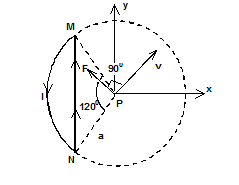
B1 = \(\frac{{{\mu }_{0}}\,I}{4\pi \,d}\,\left( \sin \,\alpha \,\,+\,\,\sin \beta \right)\)
And B2 = \(\frac{{{\mu }_{0}}\,I\,\varphi }{4\,\pi \,r}\)
So in accordance with Right hang screw roule,
\(\left( \overrightarrow{B}{{\,}_{W}} \right)\,\,=\,\,\frac{{{\mu }_{0}}}{4\pi }\,\frac{1}{\left( a\,\cos \,60 \right)}\,\,x\,\,2\,\sin \,60\,(-\hat{k})\)
and \({{\left( \overrightarrow{B}\, \right)}_{MN}}\,\,=\,\,\frac{{{\mu }_{0}}}{4\pi }\,\frac{I}{a}\,\,x\,\left( \frac{2}{3}\pi \right)\,(-\hat{k})\)
and hence net \(\overrightarrow{B}\) at P due to the given loop
\(\vec{B}={{\vec{B}}_{w}}+{{\vec{B}}_{A}}\) Þ \(\overrightarrow{\,B\,}\,\,=\,\,\frac{{{\mu }_{0}}}{4\pi \,}\,\frac{2I}{a}\left[ \sqrt{3}\,\,-\,\,\frac{\pi }{3} \right]\,\left( -\hat{k} \right)\) (i)
Now as force on charged particle in a magnetic fields is given by
\(\overrightarrow{\,F\,}\,\,=\,\,q\left( \overrightarrow{v}x\overrightarrow{B} \right)\)
so here, \(\overrightarrow{\,F\,}\,\,=\,\,q\,v\,B\,\sin \,{{90}^{0}}\,\,along\,\,PF\)
i.e. \(\overrightarrow{F}\,\,=\,\,\frac{{{\mu }_{0}}}{4\pi }\,\frac{2\,qvI}{a}\,\left[ \sqrt{3}\,-\,\frac{\pi }{3} \right]\,\,\,along\,\,PF\)
and so \(\vec{a}\,\,=\,\,\frac{\overrightarrow{F}}{m}\,\,=\,\,{{10}^{-7}}\,\frac{2\,qvI}{a}\,\left[ \sqrt{3}\,-\,\frac{\pi }{3} \right]\,\,\,along\,\,PF\)
-
MAGNETISM
Case I:
When place of the loop is perpendicular to magnetic field \(\ell \)
Length of AB = DC =
And that of BC = AD = b
Forces experienced by all the sides are shown in the figure
\ Force on AB and DC are equal and opposite to the each other and that on BC and AD too.
Þ SF = 0
Since the line of action of the forces on AB and DC is same and also the line of action of the forces BC and AD is same, therefore torque is zero.
Case II:
When the plane of the loop is inclined to the magnetic field.
In this case again SF = 0
\ Lines of action of the forces on AB and DC are different, therefore this forms a couple and produces a torque. Side view of the loop is shown in the figure.
Torque = BIl(bsinq) = BI(lb)sinq
Þ BIAsinq.
If loop has N turns then
t = BNIA sin q
In vector form
\(\vec{\tau }=\vec{\mu }\times \vec{B}\), where, \(\vec{\mu }=NI\vec{A}\)Energy needed to rotate the loop through an angle dq is
dU = tdq
Þ DU = \(\int{dU}=\int\limits_{{{\theta }_{1}}}^{{{\theta }_{2}}}{\tau d\theta }=\int\limits_{{{\theta }_{1}}}^{{{\theta }_{2}}}{\mu B\sin \theta d\theta }\)
DU = mB(cosq1 - cosq2), if we choose at q1 such that at q = q1, U1 = 0
This is the energy stored in the loop.
U = -\({{\vec{\mu }}_{m}}.\vec{B}\)
1. A magnetic field is produced and directed along y-axis. A magnet is placed along y- axis. The direction of torque on the magnet is
Solution:
In the x-y plane
2. If a bar magnet of moment is suspended in a uniform magnetic field it is given an angular deflection, w.r.t equilibrium position. Then the restoring torque on the magnet is
Solution:
MB tan \(\theta \)
1.
A wire loop carrying a current I is placed in the x-y plane as shown in fig. If an external uniform magnetic induction \(\vec{B}\,=B\hat{i}\) is applied, find the force and torque acting on the loop.
Solution:
As d\(\overrightarrow{\,F\,}\,\,=\,\,Id\,\overrightarrow{L\,}\,x\,\overrightarrow{\,B\,},\,\,\,so\,\,\,\overrightarrow{\,F\,}\,\,=\,\,\int_{{}}^{{}}{Id\overrightarrow{\,L\,}\,x\,\overrightarrow{\,B\,}}\)
As here I and \(\overrightarrow{B}\) are constant
\(\overrightarrow{F}\,=\,\,I\,\left[ \oint{d\overrightarrow{L}} \right]\,x\,\overrightarrow{B}\,\,=\,\,0\left[ as\,\,\oint{d\,\overrightarrow{L}\,\,=\,\,0} \right]\)
Further as area of coil,
\(\overrightarrow{S}\,\,=\,\,\left[ \frac{1}{3}\,\pi \,{{a}^{2}}\,\,-\,\,\frac{1}{2}\,.\,2a\,\sin {{60}^{0}}\,x\,a\,\cos {{60}^{0}} \right]\,\hat{k}\,\,=\,\,{{a}^{2}}\,\left[ \frac{\pi }{3}\,\,-\,\,\frac{\sqrt{3}}{4} \right]\hat{k}\)
so \(\overrightarrow{M}\) = \(I\,\overrightarrow{\,S\,}\,\,=\,\,I{{a}^{2}}\,\left[ \frac{\pi }{3}\,\,-\,\,\frac{\sqrt{3}}{4} \right]\,\hat{k}\)
and hence \(\overrightarrow{\tau }\,\,=\,\,\overrightarrow{M}\,\,x\,\,\overrightarrow{B}\,\,=\,\,I\,{{a}^{2}}B\,\left[ \frac{\pi }{3}\,\,-\,\,\frac{\sqrt{3}}{4} \right]\,\left( \hat{k}\,x\hat{i} \right)\,\,\)
i.e. \(\overrightarrow{\tau }\,\,=\,\,I{{a}^{2}}\,B\,\,\left[ \frac{\pi }{3}\,\,-\,\,\frac{\sqrt{3}}{4} \right]\,\hat{j}\,N-mas\,\left( \hat{k}\,x\hat{i}\,\,=\,\hat{j} \right)\)
1. The coil of a galvanometer has 500 turns and each turns has an average area 3 ´ 10-4 m2. Calculate the magnetic moment of the coil when a current of 0.5 A passes through it. If a torque of 1.5 Nm is required for this coil carrying same current to set it parallel to a magnetic field, calculate the strength of the magnetic field.
Solution:
The magnetic moment of a current loop
m = NI A = 500 x 0.5 x 3 x 10-4 = 0.075 Am2.
Also \(\vec{\tau }\,=\,\vec{\mu }\,x\,\vec{B}\,\,or\,\,\,|\vec{\tau }|\,\,=\,\,\mu \,B\,\sin \theta \)
Where q = angle between B and A
Here, q =900
\(\therefore \tau \,\,=\,\,\mu \,B\,\sin {{90}^{0}}\)
B = \(\frac{\tau }{\mu }\,\,=\,\,\frac{1.5}{0.075}\,\,=\,\,20\,T\)
2. The rectangular coil having 100 turns is turned in a uniform magnetic field of \(\frac{0.05}{\sqrt{2}}\,\,\hat{j}\) Tesla as shown in the figure. The torque acting on the loop
Solution:
The magnetic dipole moment of the current carrying coil is given by \(\vec{m}=NIA\hat{n}\)
= 100 ´ 0.5 ´ 0.08 ´ 0.04 î
= 1.6 ´ 10-2 Am2The torque acting on the coil is
\(\vec{\tau }=\vec{m}\times \vec{B}\)
\(=mB\,(\hat{i}\times \hat{j})\)
\(=1.6\times {{10}^{-2}}\times \frac{0.05}{\sqrt{2}}\hat{k}\)
= 5.66 ´ 10-4 (N - m)\(\hat{k}\)1. What is the work done in transferring the wire from position (1) to position (2)
Solution:
The loop can be thought of being made of elementary loops.
The net current in the dotted wires is 0 as current in the neighbouring loops flowing through the same wire are opposite in direction.
The 'dm' magnetic moment of the elemental loop = I2ldr.
The B at that point due to straight wire
= m0I1/2pr.
dU = -B.dm = \(-\frac{{{\mu }_{0}}{{I}_{1}}}{2\pi r}{{I}_{2}}\ell dr\,\,(\cos \,\pi )\)
[As dm is anti-parallel to B.]
\({{U}_{1}}=\int{du=\frac{{{\mu }_{o}}{{I}_{1}}{{I}_{2}}\ell }{2\pi }\int_{a}^{b}{\frac{1}{r}dr=}\frac{{{\mu }_{o}}{{I}_{1}}{{I}_{2}}\ell }{2\pi }\ln \left( \frac{b}{a} \right)}\)
By symmetry, U2 = -U1
\(\Rightarrow -\Delta U=work\,\,done\,\,=-({{U}_{2}}-{{U}_{1}})=2\frac{{{\mu }_{o}}{{I}_{1}}{{I}_{2}}\ell }{2\pi }\ln \frac{b}{a}\).
The work done in transferring the wire from position 1 to 2
= \(\frac{{{\mu }_{o}}{{I}_{1}}{{I}_{2}}\ell }{\pi }\ln \frac{b}{a}\).
2.
A wire loop carrying a current I is placed in the x-y plane as shown in fig. If a
particle with charge q and mass m is placed at the centre P and given a velocity v along NP find its instantaneous acceleration.
Solution:
As in case of current-carrying straight conductor and arc, the magnitude of B is given by
B1 = \(\frac{{{\mu }_{0}}\,I}{4\pi \,d}\,\left( \sin \,\alpha \,\,+\,\,\sin \beta \right)\)
And B2 = \(\frac{{{\mu }_{0}}\,I\,\varphi }{4\,\pi \,r}\)
So in accordance with Right hang screw roule,
\(\left( \overrightarrow{B}{{\,}_{W}} \right)\,\,=\,\,\frac{{{\mu }_{0}}}{4\pi }\,\frac{1}{\left( a\,\cos \,60 \right)}\,\,x\,\,2\,\sin \,60\,(-\hat{k})\)
and \({{\left( \overrightarrow{B}\, \right)}_{MN}}\,\,=\,\,\frac{{{\mu }_{0}}}{4\pi }\,\frac{I}{a}\,\,x\,\left( \frac{2}{3}\pi \right)\,(-\hat{k})\)
and hence net \(\overrightarrow{B}\) at P due to the given loop
\(\vec{B}={{\vec{B}}_{w}}+{{\vec{B}}_{A}}\) Þ \(\overrightarrow{\,B\,}\,\,=\,\,\frac{{{\mu }_{0}}}{4\pi \,}\,\frac{2I}{a}\left[ \sqrt{3}\,\,-\,\,\frac{\pi }{3} \right]\,\left( -\hat{k} \right)\) (i)
Now as force on charged particle in a magnetic fields is given by
\(\overrightarrow{\,F\,}\,\,=\,\,q\left( \overrightarrow{v}x\overrightarrow{B} \right)\)
so here, \(\overrightarrow{\,F\,}\,\,=\,\,q\,v\,B\,\sin \,{{90}^{0}}\,\,along\,\,PF\)
i.e. \(\overrightarrow{F}\,\,=\,\,\frac{{{\mu }_{0}}}{4\pi }\,\frac{2\,qvI}{a}\,\left[ \sqrt{3}\,-\,\frac{\pi }{3} \right]\,\,\,along\,\,PF\)
and so \(\vec{a}\,\,=\,\,\frac{\overrightarrow{F}}{m}\,\,=\,\,{{10}^{-7}}\,\frac{2\,qvI}{a}\,\left[ \sqrt{3}\,-\,\frac{\pi }{3} \right]\,\,\,along\,\,PF\)