-
CURRENT ELECTRICITY

A Wheatstone bridge is an electric circuit used to measure an unknown electrical resistance by balancing two legs of a bridge circuit, one leg of which includes the unknown component. The primary benefit of the circuit is its ability to provide extremely accurate measurements (in contrast with something like a simple voltage divider) Its operation is similar to the original potentiometer.
Bridge is balanced when galvanometer current is zero.
ii) condition for balance is \(\frac{P}{Q}=\frac{R}{S}\) (or) PS = QR.
iii)The two ends of Galvanometer remain at same potential.
The Wheatstone Bridge was originally developed by Charles Wheatstone to measure unknown resistance values and as a means of calibrating measuring instruments, voltmeters, ammeters, etc, by the use of a long resistive slide wire.
Although today digital multimeters provide the simplest way to measure a resistance. The Wheatstone Bridge can still be used to measure very low values of resistances down in the milli-Ohms range.
The Wheatstone bridge (or resistance bridge) circuit can be used in a number of applications and today, with modern operational amplifiers we can use the Wheatstone Bridge Circuit to interface various transducers and sensors to these amplifier circuits.
The Wheatstone Bridge circuit is nothing more than two simple series-parallel arrangements of resistances connected between a voltage supply terminal and ground producing zero voltage difference between the two parallel branches when balanced. A Wheatstone bridge circuit has two input terminals and two output terminals consisting of four resistors configured in a diamond-like arrangement as shown
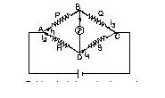
if \(\frac{P}{Q}=\frac{R}{S}\)
The bridge is balanced. Under balanced condition, points B and D are at same potential and no current flows through the resistance G. Therefore, while calculating the equivalent resistance between A and C, the resistance G is not considered,
\(\frac{1}{{{R}_{\text{eq}}}}=\frac{1}{(P+Q)}+\frac{1}{(R+S)}\) …(i)
It is interesting to note that under balanced conditions, the points B and D may be treated as shorted, so that the equivalent circuit becomes as shown. The equivalent resistance between A and C is then given as
\({{R}_{eq}}=\frac{P\times R}{P+R}+\frac{Q\times S}{Q+S}\) …(ii)
The result obtained from Eqn (ii) will be the same as that obtained from Eqn (i)
If P = Q = R = S = r, which is usually the case is most of the problems, Req = r.
1) If identical resistances (or capacitances, or inductances, or any combinations of them) are connected to form a Wheatstone bridge, the net resistance of the bridge is same as the individual resistance. So if 5 capacitances, each of value 1 mF are connected to form a Wheatstone bride, the net capacitance would be 1 mF.
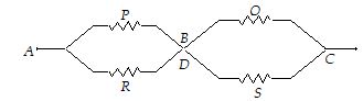
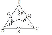
(2) Following are some of the network which appear to be different from each other, but electrically all are same as Wheatstone bridge :
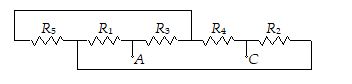
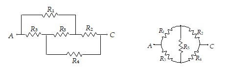

In all the circuits, if R1/R2 = R3/R4, the bridge is balanced. Then the resistance R5 can be ignored altogether.
(3) If the wheatstone bridge is not balanced or Req is to be calculated between points other than A and C, above theory will not hold good and the problem must be solved by applying Kirchhoff’s laws.
Uses of a wheat stone bridge :
i) We can compare two unknown resistances R and S from\(\frac{P}{Q}=\frac{R}{S}\).
ii) If the value of ‘S’ is also known, we can calculate the value of unknown resistance.
iii) The small strains produced in hard materials can be measured accurately with Wheatstone bridge using a strain gauge.
Galvanometer
an instrument for detecting and measuring small electric currents
A galvanometer detects the presence of current in the branch where it is connected.
It is the basic instrument used in making various meters, such
(i) ammeter (measures current)
(ii) voltmeter (measures voltage or potential difference)
(iii) ohmeters (measures resistance)
(iv) powermeter (measures power).
A galvanometer can detect a current as low as 10–9 A.
- In DC circuits, usually moving coil type galvanometers are used. Its deflection is directly proportional to the current that passes through it, or
I µ q or I = Kq
where K is called galvanometer constant.
- The deflection per unit current is called current sensitivity of the galvanometer,
\(CS=\frac{\theta }{I}=\frac{1}{K}\)
Shunting a galvanometer decreases its sensitivity. (When a small resistance is connected in parallel with a large resistance, we say that the large resistance is shunted).
- The total resistance of the galvanometer between its two terminals is called galvanometer resistance and is represented by G.
- The current required for full-scale deflection in a galvanometer is called full-scale deflection current and is represented by Ig.
Operation:
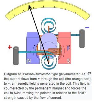
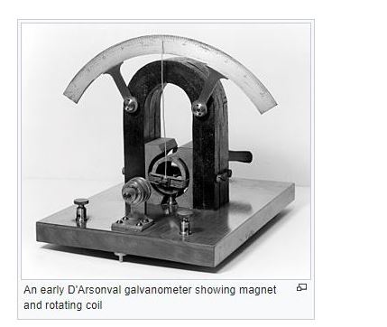
Modern galvanometers, of the D'Arsonval/Weston type, are constructed with a small pivoting coil of wire in the field of a permanent magnet. The coil is attached to a thin pointer that traverses a calibrated scale. A tiny torsion spring pulls the coil and pointer to the zero position.
When a direct current (DC) flows through the coil, the coil generates a magnetic field. This field acts against the permanent magnet. The coil twists, pushing against the spring, and moves the pointer. The hand points at a scale indicating the electric current. Careful design of the pole pieces ensures that the magnetic field is uniform, so that the angular deflection of the pointer is proportional to the current. A useful meter generally contains provision for damping the mechanical resonance of the moving coil and pointer, so that the pointer settles quickly to its position without oscillation
The basic sensitivity of a meter might be, for instance, 100 microampers full scale (with a voltage drop of, say, 50 millivolts at full current). Such meters are often calibrated to read some other quantity that can be converted to a current of that magnitude. The use of current dividers, often called shunts, allows a meter to be calibrated to measure larger currents. A meter can be calibrated as a DC voltmeter if the resistance of the coil is known by calculating the voltage required to generate a full scale current. A meter can be configured to read other voltages by putting it in a voltage divider circuit. This is generally done by placing a resistor in series with the meter coil. A meter can be used to read resistance by placing it in series with a known voltage (a battery) and an adjustable resistor. In a preparatory step, the circuit is completed and the resistor adjusted to produce full scale deflection. When an unknown resistor is placed in series in the circuit the current will be less than full scale and an appropriately calibrated scale can display the value of the previously unknown resistor.
These capabilities to translate different kinds of electric quantities, in to pointer movements, make the galvanometer ideal for turning output of other sensors that outputs electricity (in some form or another), into something that can be read by a human.
Because the pointer of the meter is usually a small distance above the scale of the meter, parallax error can occur when the operator attempts to read the scale line that "lines up" with the pointer. To counter this, some meters include a mirror along the markings of the principal scale. The accuracy of the reading from a mirrored scale is improved by positioning one's head while reading the scale so that the pointer and the reflection of the pointer are aligned; at this point, the operator's eye must be directly above the pointer and any parallax error has been minimized.
Ammeter
An ammeter is an instrument which reads the current passing through it. The ammeter must be inserted into the branch so that the current to be measured passes through it. That is, an ammeter is connected in series with the element through which current is to measured.
- The reading of an ammeter is always lesser than the actual current in the circuit. If V is the potential difference across a resistance R, the true current is I = (V/R). However, when an ammeter of resistance r is used to measure it, the reading will be
\({I}'=\frac{V}{(R+r)}\)
which is less than the true current I.
- Smaller the resistance of an ammeter, the more accurate will be its reading. An ammeter is said to be ideal if its resistance (r) is zero. However, ideal ammeter cannot be realized in practice.
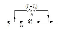
Conversion of a Galvanometer into an Ammeter
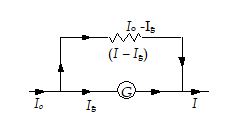
To convert a galvanometer into an ammeter of a certain range, say Io, a small resistance S (called shunt) is connected in parallel with the galvanometer. The range means the upper limit of the quantity which can be measured by the instrument. The value of S is chosen such that the current passing through the galvanometer of resistance G becomes equal to its full-scale deflection value Ig. Thus, equating the potential difference across two parallel branches, we have
\(S=\frac{{{I}_{g}}}{\text{(}{{I}_{o}}\text{ }-\text{ }{{I}_{g}})}G\)
Voltmeter:
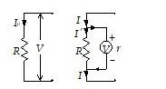
A voltmeter is an instrument which reads the potential difference across its terminals. To measure the potential difference between any two points A and B in the circuit, the voltmeter terminals are connected to A and B without breaking the circuit.
- The reading of a voltmeter is always lesser than the true value. If a current Io is passing through a resistance R, the true value V = IoR. However, when a voltmeter having resistance r is connected across R, the current through R will become
\({I}'=\frac{r}{(R+r)}{{I}_{o}}\)
and so \({V}'={I}'R=\frac{V}{[1+(R/r)]}\)
When the voltmeter is connected across R, its reading will also be V¢ which is less than V.
- Greater the resistance of voltmeter, the more accurate will be its reading. A voltmeter is said to be ideal if its resistance r is infinite. An ideal voltmeter draws no current from the circuit element for its operation.
Conversion of a Galvanometer into a Voltmeter
To convert a galvanometer into a voltmeter of certain range, say V, a high resistance R is connected in series with the galvanometer. The value of R is chosen such that the current passing through the galvanometer of resistance G becomes equal to its full-scale deflection value Ig. Thus, we should have
V = Ig(G + R) or \(R=\frac{V}{{{I}_{g}}}-\text{ }G\)

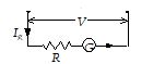
1.In the given circuit current through the galvanometer is
Solution:
Potential gradient = \(\frac{E}{r+R+{{R}_{S}}}\times \frac{R}{{{L}_{P}}}\)
=\(\frac{2}{0+15+5}\times \frac{15}{10}=0.15\)
The potential difference between A & B in the given branch of a circuit is
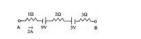
Solution:


1. What’s the effective resistance of following circuits?
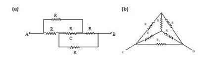
Solution:
(a)It is a Wheatstone bridge that is balanced. Hence the central resistance labeled 'C' can be pulled out.
Þ Req = R.
(b) The R11 is in parallel with a balanced Wheatstone bridge.
\(\Rightarrow {{R}_{eq}}=\frac{R.R}{R+R}=\frac{R}{2}\)
2. Calculate the voltage across the points P and R. Also find the value of resistor R4 to balance the bridge.
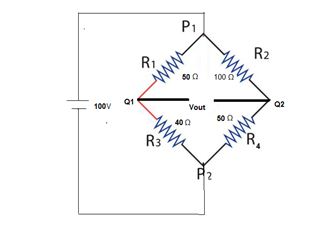
Solution:
Consider the arm P1 Q1 P2
VQ1 = R3 / (R1 + R3) * Vs
= 40 / 90 * 100
= 0.44 * 100
= 44 V
Consider the next arm P1 Q2 P2
V Q2 = R4 / R2 + R4 * VS
= 50 / (100+ 50) * 100
= 50 / 150 * 100
= 0 .33 * 100
= 33 V
Thus Vout = 44 – 33 = 11 V.
The value of resistor R4 for balancing the bridge = R2 R3 / R1
= 140 / 50
= 2.8 Ω

1.What is the value of shunt which passes 10% of the main current through a galvanometer of 99 ohms.
Solution:
As the shunt is a small resistance S in parallel with a galvanometer (of resistance G),
(Io – Ig)S = Ig* G.
or \(S=\frac{{{I}_{g}}G}{(I-{{I}_{g}})}\)
Here, G = 99 W and
Ig = (10/100) Io = 0.17
\ \(S=\frac{0.1{{I}_{o}}\times 99}{(I-0.1\,{{I}_{o}})}=\frac{0.1}{0.9}\times 99\) = 11 W
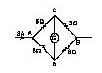
2.Calculate the equivalent resistance of the networks shown, between the points A and C.
Solution:
A careful study reveals that these networks are balanced wheatstone bridge as (P/Q) = (R/S). No current flows through resistance G. Its presence or absence does not affect the bridge.
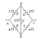
Req = (2 + 3) 11 (4 + 6) = 5 11 10 = \(\frac{5\times 10}{5+10}=\frac{\text{10}}{\text{3}}\text{ }\!\!\Omega\!\!\text{ }\)
Req = (R + R)||(R + R) = 2R||2R = R
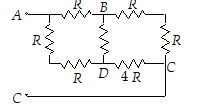
Req = (R + 2R)||(2R + 4R) = 3R||6R = 2R.

A battery of emf 1.4 V and internal resistance 2 W is connected to a resistor of 100 W. In order to measure the current through the resistance and the potential difference across its ends, an ammeter is connected in series with it and a voltmeter is connected across its ends. The resistance of the ammeter is 4/3W and that of the voltmeter is 200 W. What are the readings of the two instruments ? What would be their reading if they were ideal instruments ?
Solution:
Let RA and RV be the resistances of the ammeter and voltmeter respectively. Then the total resistance across the emf E is
Req = \(\frac{R{{R}_{V}}}{R+{{R}_{V}}}+{{R}_{A}}+r=\frac{100\times 200}{100+200}+\frac{4}{3}+2\) = \(\frac{210}{3}\) W
Therefore, the current
\({{I}_{o}}=\frac{E}{{{R}_{eq}}}=\frac{1.4}{(210/3)}\) = 0.02 A
This is the current through ammeter. Hence, the reading of ammeter is 0.02 A.
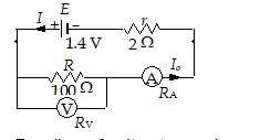
Reading of voltmeter = pd across its terminals
= \({{I}_{o}}\left( \frac{R{{R}_{V}}}{R+{{R}_{V}}} \right)=0.02\left( \frac{100\times 200}{100+200} \right)=\)1.33 V
If the ammeter and the voltmeter were ideal,
RA = 0 and RV = ¥. Then,
The reading of ammeter = \(\frac{E}{r+R}=\frac{1.4}{2+100}\)
= 0.0137 A
The reading of voltmeter = \({{I}_{o}}R=\frac{1.4}{102}\times 100\)
= 1.37 V