-
COMBINATION OF RESISTORS
COMBINATION OF RESISTORS
In preceding sections, we learnt about some simple electric circuits. We have noticed how the current through a conductor depends upon its resistance and the potential difference across its ends. In various electrical gadgets, we often use resistors in various combinations. We now, therefore, intend to see how ohm’s law can be applied to the combination of resistors.
There are two methods of joining the resistors together.
- Figure 12.6 shows an electric circuit in which three resistors having resistances R1, R2 and R3, respectively, are joined end to end. Here the resistors are said to be connected in series.
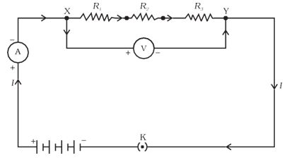
Figure 12.6: resistors in series
- Figure 12.7 shows a combination of resistors in which three resistors are connected together between points X and Y. Here, the resistors are said to be connected in parallel.
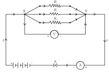
Figure 12.7: resistors in parallel
Source: This topic is taken from NCERT TEXTBOOK
-
RESISTORS IN SERIES
RESISTORS IN SERIES
What happens to the value of current when a number of resistors are connected in series in a circuit? What would be their equivalent resistance? Let us try to understand these with the help of the following activities.
Activity 12.4:
* Join three resistors of different values in series. Connect them with a battery, an ammeter and a plug key, as shown in Fig. 12.6. You may use the resistors of values like 1 \(\Omega\), 2 \(\Omega\), 3 \(\Omega\) etc., and a battery of 6 V for performing this Activity.
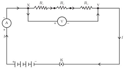
Figure 12.6: Resistors in series
* Plug the key. Note the ammeter reading.
* Change the position of the ammeter to anywhere in between the resistors. Note the ammeter reading each time.
* Do you find any change in the value of current through the ammeter?
You will observe that the value of the current in the ammeter is the same, independent of its position in the electric circuit. It means that in a series combination of resistors the current is the same in every part of the circuit or the same current through each resistor.
Activity12.5:
* In Activity 12.4, insert a voltmeter across the ends X and Y of the series combination of three resistors, as shown in Fig. 12.6.
* Plug the key in the circuit and note the voltmeter reading. It gives the potential difference across the series combination of resistors. Let it be V. Now measure the potential difference across the two terminals of the battery. Compare the two values.
* Take out the plug key and disconnect the voltmeter. Now insert the voltmeter across the ends X and P of the first resistor, as shown in Fig. 12.8.
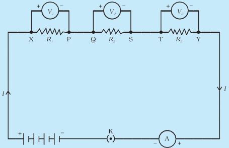
Figure 12.8:
* Plug the key and measure the potential difference across the first resistor. Let it be V1.
* Similarly, measure the potential difference across the other two resistors, separately. Let these values be V2 and V3, respectively.
* Deduce a relationship between V, V1, V2 and V3.
You will observe that the potential difference V is equal to the sum of potential differences V1, V2, and V3. That is the total potential difference across a combination of resistors in series is equal to the sum of potential difference across the individual resistors. That is,
V = V1 + V2 + V3 ............(12.11)
In the electric circuit shown in Fig. 12.8, let 'I' be the current through the circuit. The current through each resistor is also 'I'. It is possible to replace the three resistors joined in series by an equivalent single resistor of resistance R, such that the potential difference V across it, and the current 'I' through the circuit remains the same. Applying Ohm’s law to the entire circuit, we have
V = I R ............ (12.12)
On applying Ohm’s law to the three resistors separately, we further have
V1 = I R1 ............ (12.13(a))
V2 = I R2 ............ (12.13(b))
and V3 = I R3 ............ (12.13(c))
From Eq. (12.11),
I R = I R1 + I R2 + I R3
or
Rs = R1 +R2 + R3 ............ (12.14)
We can conclude that when several resistors are joined in series, the resistance of the combination Rs equals the sum of their individual resistances, R1, R2, R3, and is thus greater than any individual resistance.
Illustration 12.7:
An electric lamp, whose resistance is 20 \(\Omega\), and a conductor of 4 \(\Omega\) resistance are connected to a 6 V battery (Fig. 12.9). Calculate
(a) the total resistance of the circuit,
(b) the current through the circuit, and
(c) the potential difference across the electric lamp and conductor
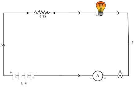
Figure 12.9: An electric lamp connected in series with a resistor of 4 \(\Omega\) to a 6 V battery
Sol:
The resistance of electric lamp, R1 = 20 \(\Omega\),
The resistance of the conductor connected in series, R2 = 4 \(\Omega\)
Then the total resistance in the circuit
R = R1 + R2
Rs = 20 \(\Omega\) + 4 \(\Omega\) = 24 \(\Omega\)
The total potential difference across the two terminals of the battery
V = 6 V.
Now by Ohm’s law, the current through the circuit is given by
I = V/Rs
= 6 V/24 \(\Omega\)
= 0.25 A.
Applying Ohm’s law to the electric lamp and conductor separately, we get potential difference across the electric lamp,
V1 = 20 \(\Omega\,\,\,\times\)0.25 A = 5 V;
and,
that across the conductor, V2 = 4\(\Omega\,\,\,\times\) 0.25 A = 1 V.
Suppose that we like to replace the series combination of electric lamp and conductor by a single and equivalent resistor. Its resistance must be such that a potential difference of 6 V across the battery terminals will cause a current of 0.25 A in the circuit. The resistance R of this equivalent resistor would be
R = V/I
= 6 V/ 0.25 A
= 24 \(\Omega\).
This is the total resistance of the series circuit; it is equal to the sum of the two resistances.
Questions
1. Draw a schematic diagram of a circuit consisting of a battery of three cells of 2 V each, a 5 \(\Omega \) resistor, an 8 \(\Omega \) resistor, and a 12 \(\Omega \) resistor, and a plug key, all connected in series.
2. Redraw the circuit of Question 1, putting in an ammeter to measure the current through the resistors and a voltmeter to measure the potential difference across the 12 \(\Omega \) resistors. What would be the readings in the ammeter and the voltmeter?
Source: This topic is taken from NCERT TEXTBOOK
-
RESISTORS IN PARALLEL
RESISTORS IN PARALLEL
Now, let us consider the arrangement of three resistors joined in parallel with a combination of cells (or a battery), as shown in Fig.12.7
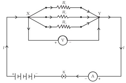
Figure 12.7: Resistors in parallel
Activity 12.6:
* Make a parallel combination, XY, of three resistors having resistances R1, R2, and R3, respectively. Connect it with a battery, a plug key and an ammeter, as shown in Fig. 12.10. Also connect a voltmeter in parallel with the combination of resistors.
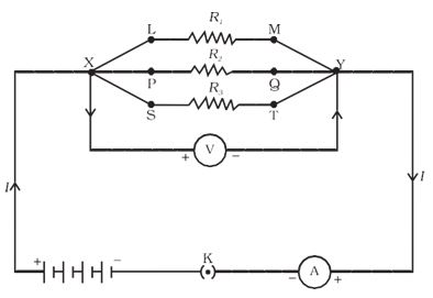
Figure 12.10:
* Plug the key and note the ammeter reading. Let the current be I. Also take the voltmeter reading. It gives the potential difference V, across the combination. The potential difference across each resistor is also V. This can be checked by connecting the voltmeter across each individual resistor (see Fig. 12.11).
* Take out the plug from the key. Remove the ammeter and voltmeter from the circuit Insert the ammeter in series with the resistor R1, as shown in Fig. 12.11. Note the ammeter reading, I1.
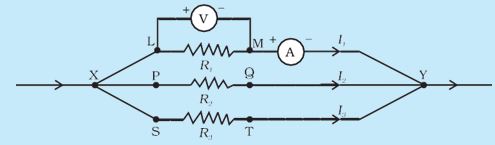
Figure 12.11:
* Similarly, measure the currents through R2 and R3. Let these be I2 and I3, respectively. What is the relationship between I, I1, I2, and I3?
It is observed that the total current I, is equal to the sum of the separate currents through each branch of the combination.
I = I1 + I2 + I3 ........... (12.15)
Let Rp be the equivalent resistance of the parallel combination of resistors. By applying Ohm’s law to the parallel combination of resistors, we have
I = V/Rp ........... (12.16)
On applying Ohm’s law to each resistor, we have
I1 = V /R1; I2 = V /R2; and I3 = V /R3 ........... (12.17)
From Eqs. (12.15) to (12.17), we have
V/Rp = V/R1 + V/R2 + V/R3
or
1/Rp = 1/R1 + 1/R2 + 1/R3 ........... (12.18)
Thus, we may conclude that the reciprocal of the equivalent resistance of a group of resistances joined in parallel is equal to the sum of the reciprocals of the individual resistances.
Illustration 12.8:
In the circuit diagram given in Fig. 12.10, suppose the resistors R1, R2 and R3 have the values 5 \(\Omega\), 10 \(\Omega\) , 30 \(\Omega\), respectively, which have been connected to a battery of 12 V. Calculate
(a) the current through each resistor,
(b) the total current in the circuit, and
(c) the total circuit resistance.
Figure 12.10:
Sol:
R1 = 5 \(\Omega\), R2 = 10 \(\Omega\) , R3 = 30 \(\Omega\),
Potential difference across the battery, V = 12 V.
This is also the potential difference across each of the individual resistor; therefore, to calculate the current in the resistors, we use Ohm’s law.
The current I1, through R1 = V/ R1
I1 = 12V/5\(\Omega\) = 2.4 A
The current I2, through R2 = V/ R2
I2 = 12V/10\(\Omega\) = 1.2 A
The current I3, through R3 = V/R3
I3 = 12V/30\(\Omega\) = 0.4 A
The total current in the circuit,
I = I1 + I2 + I3
= (2.4 + 1.2 + 0.4) A
= 4 A
The total resistance Rp, is given by [Eq. (12.18)]
\(\frac{1}{R_p}=\frac{1}{5}+\frac{1}{10}+\frac{1}{30}=\frac{1}{3}\)
Thus,
Rp= 3\(\Omega\)
Illustration 12.9:
If in Fig. 12.12, R1 = 10 \(\Omega\), , R2 = 40\(\Omega\) , R3 = 30\(\Omega\) ,R4 = 20\(\Omega\) ,R5 = 60\(\Omega\) and a 12 V battery is connected to the arrangement. Calculate
(a) the total resistance in the circuit, and
(b) the total current flowing in the circuit
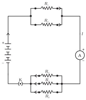
Figure 12.12: An electric circuit showing the combination of series and parallel resistors
Sol:
Suppose we replace the parallel resistors R1 and R2 by an equivalent resistor of resistance, R' . Similarly, we replace the parallel resistors R3, R4 and R5 by an equivalent single resistor of resistance R''. Then using Eq. (12.18), we have
1/ R' = 1/10 + 1/40 = 5/40; that is R' = 8 \(\Omega\).
Similarly, 1/ R'' = 1/30 + 1/20 + 1/60 = 6/60;
that is, R''= 10 \(\Omega\).
Thus, the total resistance, R = R' + R'' = 18 \(\Omega\)
To calculate the current, we use Ohm’s law, and get
I = V/R = 12 V/18 \(\Omega\) = 0.67 A
We have seen that in a series circuit the current is constant throughout the electric circuit. Thus it is obviously impracticable to connect an electric bulb and an electric heater in series because they need currents of widely different values to operate properly (see Example 12.3*). Another major disadvantage of a series circuit is that when one component fails the circuit is broken and none of the components works. If you have used ‘fairy lights’ to decorate buildings on festivals, on marriage celebrations etc., you might have seen the electrician spending lot of time in trouble-locating and replacing the ‘dead’ bulb – each has to be tested to find which has fused or gone. On the other hand, a parallel circuit divides the current through electrical gadgets. The total resistance in a parallel circuit is decreased as per Eq. (12.18). This is helpful particularly when each gadget has a different resistance and requires a different current to operate properly.
Example 12.3
(a) How much current will an electric bulb draw from a 220 V source, if the resistance of the bulb filament is 1200 \(\Omega\)?
(b) How much current will an electric heater coil draw from a 220 V source if the resistance of the heater coil is 100 \(\Omega\)?
Solution:
(a) We are given V = 220 V; R = 1200 \(\Omega\).
From Eq. (12.6), we have the current I = 220 V/1200 \(\Omega\) = 0.18 A.
(b) We are given, V = 220 V, R = 100 \(\Omega\).
From Eq. (12.6), we have the current I = 220 V/100 \(\Omega\) = 2.2 A.
Note the difference of current drawn by an electric bulb and electric heater from the same 220 V source!
Questions
1. Judge the equivalent resistance when the following are connected in parallel –
(a) 1 \(\Omega \) and 106 \(\Omega \) ,
(b) 1 \(\Omega \) and 103 \(\Omega \), and 106 \(\Omega \).
2. An electric lamp of 100 \(\Omega \), a toaster of resistance 50 \(\Omega \), and a water filter of resistance 500 \(\Omega \) are connected in parallel to a 220 V source. What is the resistance of an electric iron connected to the same source that takes as much current as all three appliances, and what is the current through it?
3. What are the advantages of connecting electrical devices in parallel with the battery instead of connecting them in series?
4. How can three resistors of resistances 2 \(\Omega \), 3 \(\Omega \), and 6 \(\Omega \) be connected to give a total resistance of (a) 4 \(\Omega \), (b) 1 \(\Omega \)?
5. What is (a) the highest, (b) the lowest total resistance that can be secured by combinations of four coils of resistance 4 \(\Omega \), 8 \(\Omega \), 12 \(\Omega \), 24 \(\Omega \)?
Source: This topic is taken from NCERT TEXTBOOK