-
HOW MAGNETIC FIELD IS CREATED?
HOW MAGNETIC FIELD IS CREATED?
Activity 13.1:
* Take a straight thick copper wire and place it between the points X and Y in an electric circuit, as shown in Fig. 13.1. The wire XY is kept perpendicular to the plane of the paper.
* Horizontally place a small compass near to this copper wire. See the position of its needle.
* Pass the current through the circuit by inserting the key into the plug.
* Observe the change in the position of the compass needle.
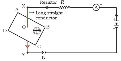
Figure 13.1:(compass needle deflection) Compass needle is deflected on passing an electric current through a metallic conductor.
In Activity 13.1, we have seen that an electric current through a metallic conductor produces a magnetic field around it. In order to find the direction of the field produced let us repeat the activity in the following way –
Activity 13.4:
* Take a long straight copper wire, two or three cells of 1.5 V each, and a plug key. Connect all of them in series as shown in Fig. 13.5 (a).
* Place the straight wire parallel to and over a compass needle.
* Plug the key in the circuit.
* Observe the direction of deflection of the north pole of the needle. If the current flows from north to south, as shown in Fig. 13.5 (a), the north pole of the compass needle would move towards the east.
* Replace the cell connections in the circuit as shown in Fig. 13.5 (b). This would result in the change of the direction of current through the copper wire, that is, from south to north.
* Observe the change in the direction of the deflection of the needle. You will see that now the needle moves in the opposite direction, that is, towards the west [Fig. 13.5 (b)]. It means that the direction of magnetic field produced by the electric current is also reversed.
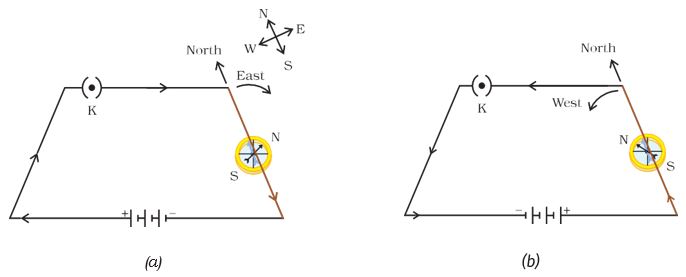
Figure 13.5: A simple electric circuit in which a straight copper wire is placed parallel to and over a compass needle. The deflection in the needle becomes opposite when the direction of the current is reversed
Source: This topic is taken from NCERT TEXTBOOK
-
MAGNETIC FIELD DUE TO A CURRENT THROUGH STRAIGHT CONDUCTOR
MAGNETIC FIELD DUE TO A CURRENT THROUGH STRAIGHT CONDUCTOR
What determines the pattern of the magnetic field generated by a current through a conductor? Does the pattern depend on the shape of the conductor? We shall investigate this with an activity.
We shall first consider the pattern of the magnetic field around a straight conductor carrying current.
Activity 13.5:
* Take a battery (12 V), a variable resistance (or a rheostat), an ammeter (0–5 A), a plug key, connecting wires, and a long straight thick copper wire.
* Insert the thick wire through the center, normal to the plane of rectangular cardboard. Take care that the cardboard is fixed and does not slide up or down.
* Connect the copper wire vertically between points X and Y, as shown in Fig. 13.6 (a), in series with the battery, a plug, and key.
* Sprinkle some iron filings uniformly on the cardboard. (You may use a salt sprinkler for this purpose.)
* Keep the variable of the rheostat at a fixed position and note the current through the ammeter.
* Close the key so that a current flows through the wire. Ensure that the copper wire placed between the points X and Y remains vertically straight.
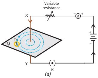
Figure 13.6(a): (magnetic field due to conductor) A pattern of concentric circles indicating the field lines of a magnetic field around a straight conducting wire. The arrows in the circles show the direction of the field lines.
* Gently tap the cardboard a few times. Observe the pattern of the iron filings. You would find that the iron filings align themselves showing a pattern of concentric circles around the copper wire (Fig. 13.6).
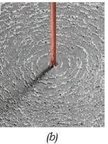
Figure 13.6(b): A close up of the pattern obtained.
* What do these concentric circles represent? They represent the magnetic field lines.
* How can the direction of the magnetic field be found? Place a compass at a point (say P) over a circle. Observe the direction of the needle. The direction of the north pole of the compass needle would give the direction of the field lines produced by the electric current through the straight wire at point P. Show the direction by an arrow
* Does the direction of magnetic field lines get reversed if the direction of current through the straight copper wire is reversed? Check it.
What happens to the deflection of the compass needle placed at a given point if the current in the copper wire is changed? To see this, vary the current in the wire. We find that the deflection in the needle also changes. In fact, if the current is increased, the deflection also increases. It indicates that the magnitude of the magnetic field produced at a given point increases as the current through the wire increases.
What happens to the deflection of the needle if the compass is moved away from the copper wire but the current through the wire remains the same? To see this, now place the compass at a farther point from the conducting wire (say at point Q). What change do you observe? We see that the deflection in the needle decreases. Thus the magnetic field produced by a given current in the conductor decreases as the distance from it increases. From Fig. 13.6, it can be noticed that the concentric circles representing the magnetic field around a current carrying straight wire become larger and larger as we move away from it.
Source: This topic is taken from NCERT TEXTBOOK
-
RIGHT HAND THUMB RULE
RIGHT-HAND THUMB RULE
A convenient way of finding the direction of the magnetic field associated with a current-carrying conductor is given in Fig. 13.7.
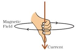
Figure 13.7: Right-hand thumb rule
Imagine that you are holding a current-carrying straight conductor in your right hand such that the thumb points towards the direction of the current. Then your fingers will wrap around the conductor in the direction of the field lines of the magnetic field, as shown in Fig. 13.7. This is known as the right-hand thumb rule.
Illustration 13.1:
A current through a horizontal power line flows in east to west direction. What is the direction of the magnetic field at a point directly below it and at a point directly above it?
Sol:
The current is in the east-west direction. Applying the right-hand thumb rule, we get that the magnetic field (at any point below or above the wire) turns clockwise in a plane perpendicular to the wire, when viewed from the east end, and anti-clockwise, when viewed from the west end.
Questions
1. Draw magnetic field lines around a bar magnet.
2. List the properties of magnetic field lines.
3. Why don’t two magnetic field lines intersect each other?
Source: This topic is taken from NCERT TEXTBOOK
-
MAGNETIC FIELD DUE TO A CURRENT THROUGH A CIRCULAR LOOP
MAGNETIC FIELD DUE TO A CURRENT THROUGH A CIRCULAR LOOP
We have so far observed the pattern of the magnetic field lines produced around a current carrying straight wire. Suppose this straight wire is bent in the form of a circular loop and a current is passed through it. How would the magnetic field lines look like? We know that the magnetic field produced by a current carrying straight wire depends inversely on the distance from it. Similarly, at every point of a current-carrying circular loop, the concentric circles representing the magnetic field around it would become larger and larger as we move away from the wire (Fig. 13.8). By the time we reach at the center of the circular loop, the arcs of these big circles would appear as straight lines. Every point on the wire carrying current would give rise to the magnetic field appearing as straight lines at the center of the loop. By applying the right-hand rule, it is easy to check that every section of the wire contributes to the magnetic field lines in the same direction within the loop.
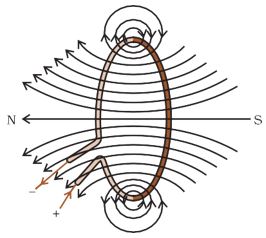
Figure 13.8: Magnetic field lines of the field produced by a current-carrying circular loop
We know that the magnetic field produced by a current-carrying wire at a given point depends directly on the current passing through it. Therefore, if there is a circular coil having n turns, the field produced is n times as large as that produced by a single turn. This is because the current in each circular turn has the same direction, and the field due to each turn then just adds up.
Activity 9.1:
* Take rectangular cardboard having two holes. Insert a circular coil having a large number of turns through them, normal to the plane of the cardboard.
* Connect the ends of the coil in series with a battery, a key, and a rheostat, as shown in Fig. 13.9.
* Sprinkle iron filings uniformly on the cardboard.
* Plug the key.
* Tap the cardboard gently a few times. Note the pattern of the iron filings that emerges on the cardboard.
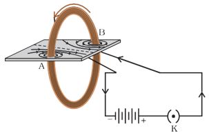
Figure 13.9 (magnetic field around circular coil): Magnetic field produced by a current-carrying circular coil
Source: This topic is taken from NCERT TEXTBOOK
-
MAGNETIC FIELD DUE TO A CURRENT IN SOLENOID
MAGNETIC FIELD DUE TO A CURRENT IN SOLENOID
A coil of many circular turns of insulated copper wire wrapped closely in the shape of a cylinder is called a solenoid. The pattern of the magnetic field lines around a current-carrying solenoid is shown in Fig. 13.10.
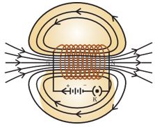
Figure 13.10 (magnetic field around solenoid): Field lines of the magnetic field through and around a current-carrying solenoid.
Compare the pattern of the field with the magnetic field around a bar magnet (Fig. 13.4). Do they look similar? Yes, they are similar.

Figure 13.4 ( solenoid-bar magnet ) : Field lines around a bar magnet
In fact, one end of the solenoid behaves as a magnetic north pole, while the other behaves as the south pole. The field lines inside the solenoid are in the form of parallel straight lines. This indicates that the magnetic field is the same at all points inside the solenoid. That is, the field is uniform inside the solenoid.
A strong magnetic field produced inside a solenoid can be used to magnetise a piece of magnetic material, like soft iron, when placed inside the coil (Fig. 13.11). The magnet so formed is called an electromagnet.
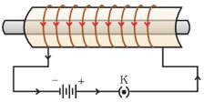
Figure 13.11 ( solenoid-electromagnet ): A current-carrying solenoid coil is used to magnetise steel rod inside it – an electromagnet
Questions
1. Consider a circular loop of wire lying in the plane of the table. Let the current pass through the loop clockwise. Apply the right-hand rule to find out the direction of the magnetic field inside and outside the loop?
2. The magnetic field in a given region is uniform. Draw a diagram to represent it.
3. Choose the correct option.
The magnetic field inside a long straight solenoid-carrying current
(a) is zero.
(b) decreases as we move towards its end.
(c) increases as we move towards its end.
(d) is the same at all points
Source: This topic is taken from NCERT TEXTBOOK