-
WHAT IS OHM’S LAW?
WHAT IS OHM’S LAW?
Is there a relationship between the potential difference across a conductor and the current through it? Let us explore with an Activity.
Activity 12.1:
* Set up a circuit as shown in Fig. 12.2, consisting of a nichrome wire XY of length, say 0.5 m, an ammeter, a voltmeter and four cells of 1.5 V each. (Nichrome is an alloy of nickel, chromium, manganese, and iron metals.)
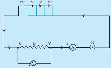
Figure 12.2: Electric circuit for studying Ohm’s law
* First use only one cell as the source in the circuit. Note the reading in the ammeter I, for the current and reading of the voltmeter V for the potential difference across the nichrome wire XY in the circuit. Tabulate them in the Table given
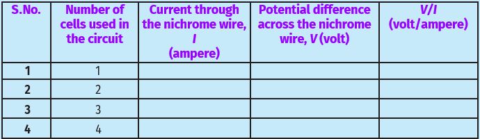
* Next connect two cells in the circuit and note the respective readings of the ammeter and voltmeter for the values of current through the nichrome wire and potential difference across the nichrome wire.
* Repeat the above steps using three cells and then four cells in the circuit separately.
* Calculate the ratio of V to I for each pair of potential difference V and current I
* Plot a graph between V and I, and observe the nature of the graph.
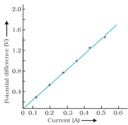
Figure 12.3: V–I graph for a nichrome wire. A straight line plot shows that as the current through a wire increases, the potential difference across the wire increases linearly – this is Ohm’s law
In this Activity, you will find that approximately the same value for V/I is obtained in each case. Thus the V–I graph is a straight line that passes through the origin of the graph, as shown in Fig. 12.3. Thus, V/I is a constant ratio.
In 1827, a German physicist Georg Simon Ohm (1787–1854) found out the relationship between the current I, flowing in a metallic wire and the potential difference across its terminals. The potential difference, V, across the ends of a given metallic wire in an electric circuit is directly proportional to the current flowing through it, provided its temperature remains the same. This is called Ohm’s law. In other words –
V \(\propto\) I ............. (12.4)
or V/I = constant = R
or V = IR ............. (12.5)
In Eq. (12.4), R is a constant for the given metallic wire at a given temperature and is called its resistance. It is the property of a conductor to resist the flow of charges through it. Its SI unit is ohm, represented by the Greek letter Ω. According to Ohm’s law,
R = V/I ............. (12.6)
If the potential difference across the two ends of a conductor is 1 V and the current through it is 1 A, then the resistance R, of the conductor is 1 Ω.
That is, \(1 \,\,ohm=\frac{1\,\,volt}{1\,\,ampere}\)
Also from Eq. (12.5) we get
I = V/R ............. (12.7)
It is obvious from Eq. (12.7) that the current through a resistor is inversely proportional to its resistance. If the resistance is doubled the current gets halved. In many practical cases, it is necessary to increase or decrease the current in an electric circuit. A component used to regulate current without changing the voltage source is called variable resistor. In an electric circuit, a device called rheostat is often used to change the resistance in the circuit. We will now study about electrical resistance of a conductor with the help of the following Activity.
Activity 12.2:
* Take a nichrome wire, a torch bulb, a 10 W bulb and an ammeter (0 – 5 A range), a plug key and some connecting wires.
* Set up the circuit by connecting four dry cells of 1.5 V each in series with the ammeter leaving a gap XY in the circuit, as shown in Fig. 12.4.
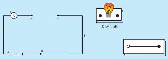
Figure 12.4:
* Complete the circuit by connecting the nichrome wire in the gap XY. Plug the key. Note down the ammeter reading. Take out the key from the plug. [Note: Always take out the key from the plug after measuring the current through the circuit.]
* Replace the nichrome wire with the torch bulb in the circuit and find the current through it by measuring the reading of the ammeter.
* Now repeat the above step with the 10 W bulb in the gap XY.
* Are the ammeter readings different for different components connected in the gap XY? What do the above observations indicate?
* You may repeat this Activity by keeping any material component in the gap. Observe the ammeter readings in each case. Analyse the observations.
In this Activity, we observe that the current is different for different components. Why do they differ? Certain components offer an easy path for the flow of electric current while others resist the flow. We know that the motion of electrons in an electric circuit constitutes an electric current. The electrons, however, are not completely free to move within a conductor. They are restrained by the attraction of the atoms among which they move. Thus, the motion of electrons through a conductor is retarded by its resistance. A component of a given size that offers a low resistance is a good conductor. A conductor having some appreciable resistance is called a resistor. A component of identical size that offers a higher resistance is a poor conductor. An insulator of the same size offers even higher resistance.
Source: This topic is taken from NCERT TEXTBOOK