-
Lines and Angles
INTRODUCTION
You already know how to identify different lines, line segments and angles in a given shape. Can you identify the different line segments and angles formed in the following figures? (Fig 5.1)
(i)
 (ii)
(ii) 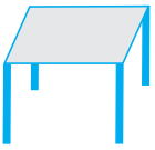 (iii)
(iii)  (iv)
(iv) 
Fig 5.1
Can you also identify whether the angles made are acute or obtuse or right? Recall that a line segment has two end points. If we extend the two end points in either direction endlessly, we get a line. Thus, we can say that a line has no end points. On the other hand, recall that a ray has one end point (namely its starting point). For example, look at the figures given below:
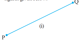
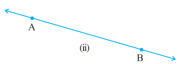

Fig 5.2
Here, Fig 5.2 (i) shows a line segment, Fig 5.2 (ii) shows a line and Fig 5.2 (iii) is that of a ray. A line segment PQ is generally denoted by the symbol PQ, a line AB is denoted by the symbol AB and the ray OP is denoted by OP u ruu . Give some examples of line segments and rays from your daily life and discuss them with your friends.
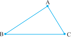
Again recall that an angle is formed when lines or line segments meet. In Fig 5.1, observe the corners. These corners are formed when two lines or line segments intersect at a point. For example, look at the figures given below:
(i)
 (ii)
(ii) 
Fig 5.3
In Fig 5.3 (i) line segments AB and BC intersect at B to form angle ABC, and again line segments BC and AC intersect at C to form angle ACB and so on. Whereas, in Fig 5.3 (ii) lines PQ and RS intersect at O to form four angles POS, SOQ, QOR and ROP. An angle ABC is represented by the symbol ∠ABC. Thus, in Fig 5.3 (i), the three angles formed are ∠ABC, ∠BCA and ∠BAC, and in Fig 5.3 (ii), the four angles formed are ∠POS, ∠SOQ, ∠QOR and ∠POR. You have already studied how to classify the angles as acute, obtuse or right angle. Note: While referring to the measure of an angle ABC, we shall write m∠ABC as simply ∠ABC. The context will make it clear, whether we are referring to the angle or its measure.
-
Lines and angles
RELATED ANGLES
Complementary Angles :
When the sum of the measures of two angles is 90°, the angles are called complementary angles.
(i)
 (ii)
(ii) 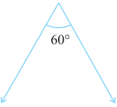 Fig 5.4 (iii)
 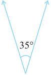 (iv)
(iv) 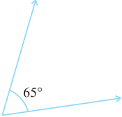
Are these two angles complementary? Yes Are these two angles complementary? No
Whenever two angles are complementary, each angle is said to be the complement of the other angle. In the above diagram (Fig 5.4), the ‘30° angle’ is the complement of the ‘60° angle’ and vice versa.
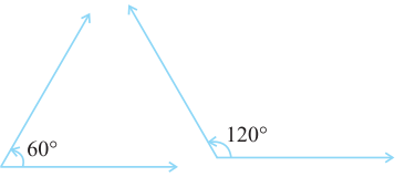
Supplementary Angles:
Let us now look at the following pairs of angles (Fig 5.6):
(i)
 (ii)
(ii) 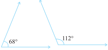
(iii)
 (iv)
(iv)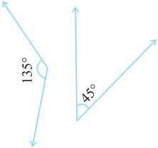
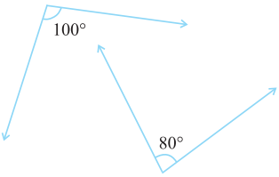
Do you notice that the sum of the measures of the angles in each of the above pairs (Fig 5.6) comes out to be 180º? Such pairs of angles are called supplementary angles. When two angles are supplementary, each angle is said to be the supplement of the other.
-
Lines and Angles
PAIRS OF LINES
Intersecting Lines:
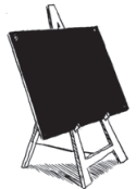
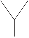
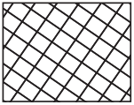
Fig 5.8
The blackboard on its stand, the letter Y made up of line segments and the grill-door of a window (Fig 5.8), what do all these have in common? They are examples of intersecting lines.
Two lines l and m intersect if they have a point in common. This common point O is their point of intersection.
Transversal:
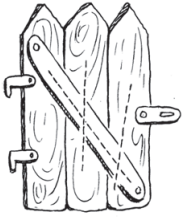
You might have seen a road crossing two or more roads or a railway line crossing several other lines (Fig 5.10). These give an idea of a transversal.
(i)
 (ii)
(ii) 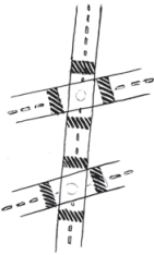
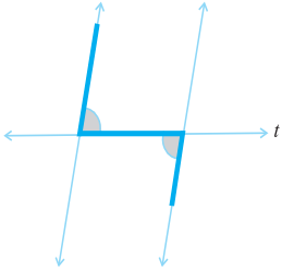
A line that intersects two or more lines at distinct points is called a transversal. In the Fig 5.11, p is a transversal to the lines l and m.
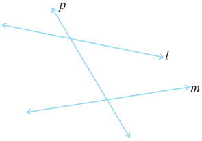
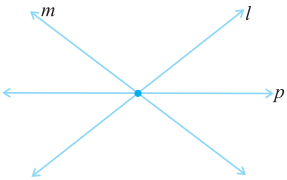
Fig 5.11 Fig 5.12
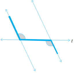
In Fig 5.12 the line p is not a transversal, although it cuts two lines l and m. Can you say, ‘why’?
Angles made by a Transversal:
In Fig 5.13, you see lines l and m cut by transversal p. The eight angles marked 1 to 8 have their special names:
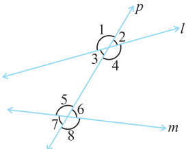 Fig 5.13
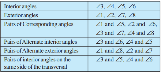
Note: Corresponding angles (like ∠1 and ∠5 in Fig 5.14) include
(i) different vertices
(ii) are on the same side of the transversal and
(iii) are in ‘corresponding’ positions (above or below, left or right) relative to the two lines.
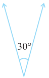

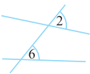
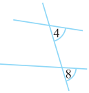
Fig 5.14
Alternate interior angles (like ∠3 and ∠6 in Fig 5.15)
(i) have different vertices
(ii) are on opposite sides of the transversal and
(iii) lie ‘between’ the two lines.
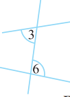
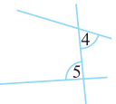
Fig 5.15
Transversal of Parallel Lines
Do you remember what parallel lines are? They are lines on a plane that do not meet anywhere. Can you identify parallel lines in the following figures? (Fig 5.16)
Fig 5.16
Transversals of parallel lines give rise to quite interesting results.
This activity illustrates the following fact:
If two parallel lines are cut by a transversal, each pair of corresponding angles are equal in measure.
We use this result to get another interesting result. Look at Fig 5.18. When t cuts the parallel lines, l, m, we get, ∠3 = ∠7 (vertically opposite angles). But ∠7 = ∠8 (corresponding angles). Therefore, ∠3 = ∠8 You can similarly show that ∠1 = ∠6. Thus, we have the following result :
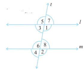 Fig 5.18
 If two parallel lines are cut by a transversal, each pair of alternate interior angles are equal.
This second result leads to another interesting property. Again, from Fig 5.18.
∠3 + ∠1 = 180° (∠3 and ∠1 form a linear pair) But ∠1 = ∠6 (A pair of alternate interior angles) Therefore, we can say that ∠3 + ∠6 = 180°. Similarly, ∠1 + ∠8 = 180°. Thus, we obtain the following result:
If two parallel lines are cut by a transversal, then each pair of interior angles on the same side of the transversal are supplementary.
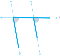
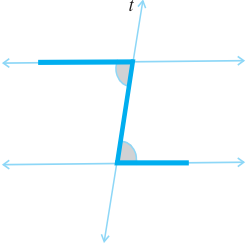
You can very easily remember these results if you can look for relevant ‘shapes’.
The F-shape stands for corresponding angles:


The Z - shape stands for alternate angles.
-
Lines and angles
CHECKING FOR PARALLEL LINES
If two lines are parallel, then you know that a transversal gives rise to pairs of equal corresponding angles, equal alternate interior angles and interior angles on the same side of the transversal being supplementary.
When two lines are given, is there any method to check if they are parallel or not? You need this skill in many life-oriented situations.
 Fig 5.19
A draftsman uses a carpenter’s square and a straight edge (ruler) to draw these segments (Fig 5.19). He claims they are parallel. How?
Are you able to see that he has kept the corresponding angles to be equal? (What is the transversal here?)
Thus, when a transversal cuts two lines, such that pairs of corresponding angles are equal, then the lines have to be parallel.
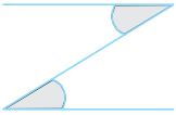 Fig 5.20
 Look at the letter Z(Fig 5.20). The horizontal segments here are parallel, because the alternate angles are equal.
When a transversal cuts two lines, such that pairs of alternate interior angles are equal, the lines have to be parallel.
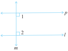 Fig 5.21
Draw a line l (Fig 5.21).
Draw a line m, perpendicular to l. Again draw a line p, such that p is perpendicular to m.
Thus, p is perpendicular to a perpendicular to l.
You find p || l. How? This is because you draw p such that ∠1 + ∠2 = 180o .
Thus, when a transversal cuts two lines, such that pairs of interior angles on the same side of the transversal are supplementary, the lines have to be parallel.