-
Symbols Of Electric Componenets
SYMBOLS OF ELECTRIC COMPONENT
Some common electric components can be represented by symbols. In Table 14.1, some electric components and their symbols are shown. You may come across different symbols for these components in different books. However, in this book, we shall be using the symbols shown here.
Look at the symbols carefully. In the symbol for the electric cell, notice that there is a longer line and a shorter but thicker parallel line. Do you recall that an electric cell has a positive terminal and a negative terminal? In the symbol of the electric cell, the longer line represents the positive terminal and the thicker, shorter line represents the negative terminal.
For a switch the ‘ON’ position and the ‘OFF’ position are represented by the symbols as shown. The wires used to connect the various components in a circuit are represented by lines
In Table 14.1, a battery and its symbol are also shown. Do you know what a battery is? Look at the symbol of a battery. Can you make out what a battery could be? For some of the activities we may need more than one cell. So, we connect two or more cells together as shown in Fig.14.2. Notice
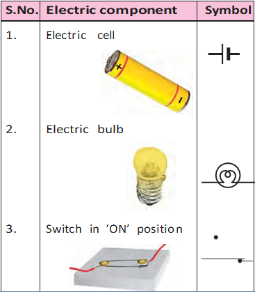
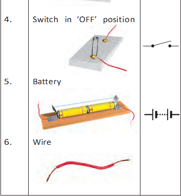
Table 14.1 SYMBOLS OF ELECTRIC COMPONENTS
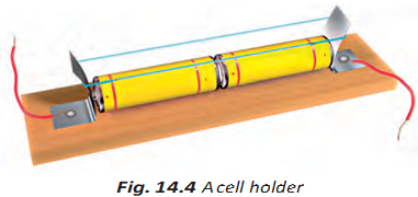
Many devices such as torches, transistors, toys, TV remote controls, use batteries. However, in some of these devices the electric cells are not always placed one after the other as shown in Fig. 14.2. Sometimes the cells are placed side by side. Then how are the terminals of the cells connected? Look carefully inside the battery compartment of any device. There is usually a thick wire or a metal strip connecting the positive terminal of one cell to the negative terminal of the next cell (Fig.14.3). In order to help you to place the cells correctly in the battery compartment, ‘+’ and ‘–’ symbols are usually printed there.
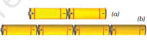
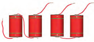
Fig. 14.2 (a) A battery of two cells
(b) A battery of four cells
Activity 14.1
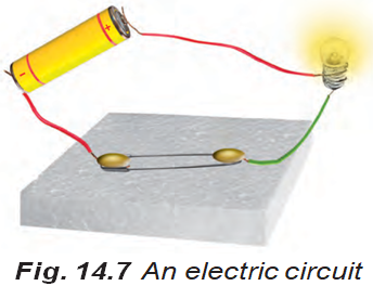
Make the electric circuit shown in Fig. 14.7. You used a similar circuit in Class VI to make an electric bulb glow. Do you remember that the bulb glows only when the switch is in the ‘ON’ position? The bulb glows as soon as the switch is moved to the ‘ON’ position.
Copy this electric circuit in your notebook. Make also a circuit diagram of this circuit using symbols for the various electric components.
Is your diagram similar to the one shown in Fig. 14.8?
It is much easier to draw a circuit diagram using symbols. Therefore, we generally represent an electric circuit by its circuit diagram
Fig. 14.9 shows another circuit diagram. Is it identical to the circuit diagram shown in Fig.14.8? In which way is it different?
Would the bulb glow in this electric circuit? Recall that the bulb glows only when the switch is in the ‘ON’ position and the electric circuit is closed.

Notice that the key or switch can be placed anywhere in the circuit.
When the switch is in the ‘ON’ position, the circuit from the positive terminal of the battery to the negative terminal is complete.
The circuit is then said to be closed and the current flows throughout the circuit instantly.
When the switch is in the ‘OFF’
position, the circuit is incomplete. It is said to be open. No current flows through any part of the circuit.
In the bulb there is a thin wire, called the filament, which
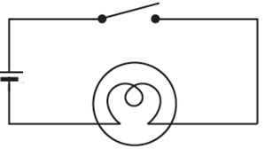
Fig. 14.9 Another circuit diagram
electric current passes through it. When the bulb gets fused, its filament is broken.
Never touch a lighted electric bulb connected to the mains. It may be very hot and your hand may get burnt badly. Do not experiment with the electric supply from the mains or a generator or an inverter. You may get an electric shock, which may be dangerous. Use only electric cells for all the activities suggested here.
If the filament of the bulb is broken,
would the circuit be complete? Would the bulb still glow?
You might have noticed that a glowing electric bulb become warm. Do you know why?